DESCRIPTION
The Philips GM 4140 bridge has been designed for the measurement of
resistances of 0,1 ohm to 10 megohm and of capacities from 1 uuF to 10
uF. However larger resistances than 10 megohm and capacities larger
than 10 uF can be measured, when their values are compared to standard
resistors and standard capacitors respectively by connecting external
standard known values to compare the value of resistance or capacity.
Furthermore inductance can be determined and compared with this
instrument and also short circuits between windings can be determined.
The capacity and resistance of electrolytic capacitors (and
consequently the loss factor) with help of a known capacity and a known
resistance can be measured. The bridge can be feed with an external
frequency source up to 10,000 Hz to measure the resistance of
electrolytic capacitors. This voltage source has to supply only 7 W at
100 V to and 11 W at 220 V.
A percentage standard scale makes it possible to measure a large
numbers capacitors, resistances and inductors quickly to reject parts
which exceed a certain tolerance. A deviation of 0,1% can be read.
A cathode ray indicator is used for determining bridge balance which
enables accurate measurements very easy and fast. Another advantage of
this indicator is that it indicates whether a lower or a higher switch
range should be used. It is important that there are no electrostatic
or magnetic fields in the vicinity of Terminal "2", for accurate
measurement. Because otherwise the high sensitivity of the indicator no
sharp minimum would be obtained. The connections from the device being
tested should be screened and connected to earth. This is why the power
cord of the instrument is shielded and connected to earth.
SETTING UP
First determine the supply voltage (100-150 V or 170-250 V). To adjust
the bridge for the other voltages, remove the four screws underneath
the unit and take the cardboard away. On the marked strip by the
transformer position "127 V" corresponds with voltages 100 V-I7O V and
position "220 V" with voltages 170 V-250 V. After adjustment the
cardboard must be carefully replaced before replacing the case.
CONNECTION
The terminal at the back of the device must be connected to earth. This
is very important when measurements of small capacities or large
resistances are to be made. Within a minute of being plugged in to the
mains supply for the bridge is ready for use.
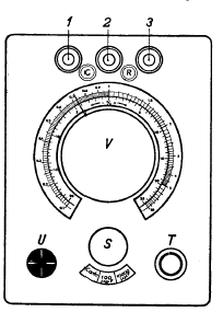
CONTROL POSITION
If knob "V" has, perhaps become twisted on its axis this can be
remedied by putting knob "S" in control position "Contr." Then with
nothing connected to terminals "1, 2 and 3", and knob" T" turned fully
clockwise adjust the bridge balance knob "V" so that the arms of the
green cross on the indicator are as narrow as possible. The pointer of
knob "V" must now be on position "1" of the scale. If this is not the
case then the knob should be loosened and carefully turned and reset in
the correct position before re-tightening.
MEASUREMENTS
a. Measurement of resistances First set "S" to the appropriate
position:
Position 1 ohms for resistances from 0,1- 10 ohm
Position 100 ohms for resistances from 10-1000 ohm.
Position 10000 ohms for resistances from 1000-100000 ohm
Position 1 Mohms for resistances from 100000 ohm-l0 megohm
The unknown resistance is then connected to the terminal "R". Bridge
balance knob" V" is adjusted so that that the arms of the cross "U" are
as narrow as possible. The value of the unknown resistance is obtained
from the indication of the outside scale multiplied with the position
of knob "S".
For the measurement of resistances larger than 10 megohm, set knob "S"
in on the "open bridge position". The unknown resistance is connected
to terminal "R" and the standard resistance with which it is to be
compared on terminals "1 and 2". After balancing using "U" with help of
knob" V" on minimum the value is found by multiplying the scale reading
with the value of the standard resistance.
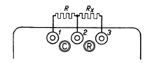
The same procedure can be used to measure of the resistance of electrolytes and other solvents. In this case it is recommended to use a voltage source with a higher frequency (e.g. 500 or 1000 Hz), to prevent electrolysis or polarisation. The "S" on open bridge can also be fed with a voltage source with a higher frequency (500 or 1000 Hz) for use with electrolytics to prevent polarization. Terminals inside the case need to be accessed to use this feature.
b. Measurement of capacities First set "S" to the
appropriate position:
Position 100 uuF for capacities from 10 uuF-1000 uuF
Position 10000 uuF for capacities from 1000 uuF-O,1 uF
Position 1 uF for capacities from 0,1 uF-I0 uF
The unknown capacitor is then connected to the terminal "C". Bridge
balance knob" V" is adjusted so that that the arms of the cross "U" are
again on the smallest width. The value of the unknown capacitance is
obtained from the indication of the outside scale multiplied by the
position of knob "S".
For the measurement of small capacities, one must however, deduct 10
uuF from the indicated value. This 10 uuF forms the precisely adjusted
internal capacitors connected between terminals "1,2 and 3". The "Open
Bridge" position "\I/" can be used for the measurement of capacities
smaller than 90 uuF (down to 1 uuF); when the bridge is balanced using
knob "V", the unknown value will be (scale reading X 10 uuF) - 10 uuF.
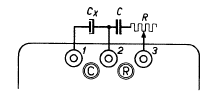
To measure of capacities larger than 10 uF connect the unknown
capacitor to terminal "C" and a similar standard capacity between "2
and 3". Turn knob "S" to the "Open Bridge" position "\I/" and after
adjusting "V" for balance the unknown capacitance = scale reading X
standard capacity.
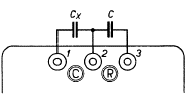
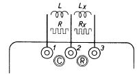
c. Measurement of electrolytic capacitors
Knob "S" is set to "Open bridge" position and the unknown capacitor
is connected to terminals "C". Connect a (loss-less) standard capacitor
with a calibrated adjustable resistor in series. The series resistor is
first set to zero. Then adjust "V" so that the arms of the cross "U"
have minimum width. Knob "T" should be turned counter clockwise a
little. If it is not possible to get a sharp null, this indicates that
the capacitor has a parasitic series resistance. The accurate balance
position can be obtained by adjusting the resistor.
At balance the capacity of the electrolytic capacitor equals the reading multiplied by the standard capacitor and the parasitic resistance of the electrolytic capacitor equals 1/reading x setting of the calibrated resistor.
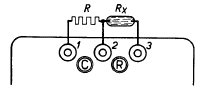
d. Measurements of inductance The unknown inductor should be connected to terminal "R" and "S" set to the "Open Bridge" position "\I/". Connect a standard inductor with a calibrated adjustable resistance in series between terminals "1 and 2". Adjust "V" and the calibrated adjustable resistor for as narrow possible indication on the cathode ray indicator.
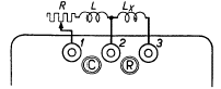
The self inductance of the unknown inductor =scale reading X
standard
inductor value, and the resistance of the unknown inductor= scale
reading X totally present resistance (totally present resistance =
resistance of the standard inductor + value of the calibrated
adjustable resistance). If two equal inductors are connected to "1 and
2" and "2 and 3" a short circuit on one will prevent a sharp minimum
being obtained. These measurements are preferably done at a higher
frequency (500 Hz).
Per cent scale To check large numbers of resistances, capacitors
and inductors are within a particular tolerance. In position "%" of
knob "S" one can quickly measure the deviation in percent of the
comparisons standard (- 20% to + 25%) within a deviation of 0.1%.
For capacitors, the capacitor to be checked is connected to the terminal "C" and the comparison standard connected to "2 and 3" . Bridge balance knob "V" is used to indicate how many per cent it is larger or is smaller than the comparison standard. This measurement can be done at reduced sensitivity, which is a very fast way for rough checking, (see below).
For resistances and self inductances the parts to be checked are
connected to the terminal "R" and the comparisons standard connected to
"1 and 2".
Sensitivity adjustment The highest sensitivity is obtained when
knob " T" has been turned fully clockwise. In this position, best
accuracy is obtained. For quick measurements it is advised to turn
knob" T" a little anti-clockwise. This is also of interest for the
measurement of capacities or inductance with a loss resistance that
otherwise no minimum can be obtained, before the resistance elements
have been brought into balance. Finally, to measure a completely
unknown capacity or resistance reducing the sensitivity is in order.
Begin with an arbitrary range on switch "S" and adjust knob "T" so
that the arms of" U" approximately 6 mm wide. Turn bridge balance knob
"V" clockwise and if the arms of the cross narrow without a sharp
minimum, then this indicates that a higher range must be used. If the
arms become narrower when knob "V" is turned anti-clockwise then a
lower range should be used.