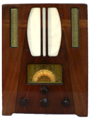
Burndept 252 AC/DC TRF veneered wood case (original valves VP1321,SP13C,PEN36C,1D5) valves fitted EF39 ,SP13 ,CL33, 4020 Long /medium /2 short working UK 1936 (I have circuit diagram)
I have had this set since the mid 1980's and originally it was incapable of producing even the slightest hum. This is an AC/DC TRF 4 waveband (Long /medium /2 short) receiver housed in a veneered wood case (original valves VP1321,SP13C,PEN36C,1D5) The set had been modified and the VP132 had been replaced with an EF39, the PEN36 with a CL33, and the 1D5 with a 4020. The original dry electrolytic smoothing capacitors had also been replaced by a relatively modern tubular unit. The dial indicates that it was made in Austria and some of the capacitors (SARTOR) have a date code which might indicate that they were made in 1935. The service sheet which also covers the Vidor model 254 indicates that the release date for both models was 1936 and the original price was �9 9s. This is equivalent to over �300 today!
I soon discovered that the rectifier was duff and by powering the set with an external 250v DC supply found that the output stage was not working (it was glowing blue!). Though by taking the grid connection to an external amplifier and speaker it was clear that there was little wrong with the first two stages apart from noisy wave change switch and gain control.
Two new valves were needed, I decided that since the holders had been replaced for the EF39 and the CL33 and that the first two stages were working that I would purchase an 1D5 and a CL33 from [email protected] and in the meantime attend to the rest of the set. The electrolytic capacitors appeared to work fine after an hour or two reforming, though the mains and speaker leads and three capacitors needed replacing.
The cabinet rubbed down and re polished and the speaker cloth was replaced. The celluloid dial had curved inwards over the years and was stiffened and straightened by making two thin U sections from tin plate and slipping them over the top and bottom edges of the dial. When the valves arrived the mains tapping was set to 240v (to compensate for the lower heater voltage of the EF39) and the set energised via a 100watt light bulb. It worked on all wavebands and after half an hour the set was energised directly and the voltages checked out more or less as per the service sheet. Some minor adjustment of the trimmer capacitors was necessary to obtain maximum output.
How much is it worth? £30

