Serial number 104488
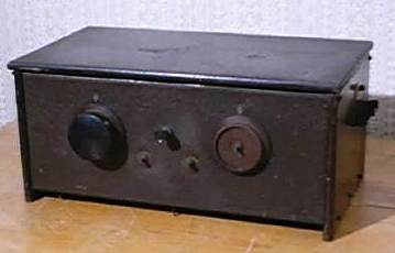
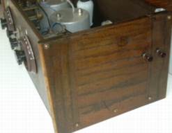
Before and after cleaning and rebuilding
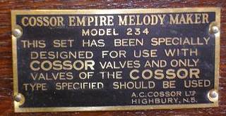
Cossor Battery TRF kit Radio UK 1929/1930 I acquired this incomplete, sorry looking wireless set as part of an auction lot in 2004.Two valve holders four knobs and an inter valve transformer had at sometime in the past been removed and used for something else. A toggle switch and two additional terminals had been added to the right hand side of the set and the metal chassis was dirty and very rusty.The rubber insulation on the wires from the screened coils had perished and the valves I received with the set did not seem to be original. (Eveready K40N, Ediswan PV6DE and Cossor 210 LF) and the internal label was not exactly helpful in this respect!
The first job was to dismantle the set completely remove the rust from the baseplate and make good the holes vacated by the additional terminals and toggle switch. Once this was done the wooden side panels and the hinged lid were stripped, lightly sandpapered and stained prior to being given a light coating of shellac varnish. The brown crackle finished front and back panels were washed, dried and touched up with brown cellulose paint prior to being given a light spray. The steel base panel was covered with a thin coating of silver coloured paste (used for renovating picture frames) applied with an old toothbrush and a piece of cloth. In UK this is called 'Goldfinger' and manufactured by Rowney.
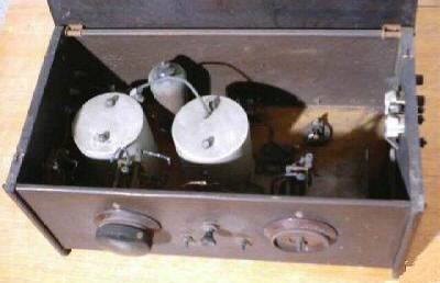
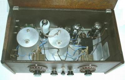
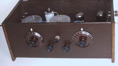
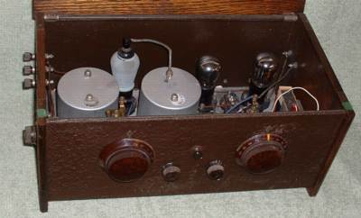
Views of interior before and after rebuilding
The terminals and brass parts were treated with dilute hydrochloric acid (lavatory cleaner) then thoroughly washed, rinsed and dried prior to re-assembly. I found that the green TCC 0.1 mFd capacitor had failed, so I unsoldered the casing and inserted a modern replacement in place of the wax insulated component.I also found that the toggle switches in the base of the coil cans were not opening and closing properly. After a good dowsing of switch cleaner and a few operations reliable contact was enabled once more. I made careful note of the orientation of the coils and how they had been connected prior to replacing all the flying leads. As I did not have a spare inter valve transformer to hand, a substitute resistance capacitance arrangement hidden inside the plastic casing which once housed a PP9 battery was made and mounted in its place.
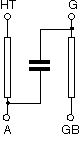
220k HT to Anode 470K Grid to Grid bias and 0.1mFd coupling
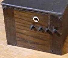
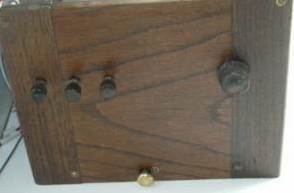
Note the toggle switch and two additional brass terminals which
have now been removed and the brass wave change lever
(push in for Long Wave).
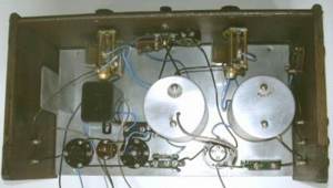
View of interior of another apparently complete Cossor 234
radio
If you want to know more about Cossor radios look at this great
site:
http://www.cossor.co.uk/home

