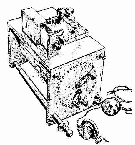
The picture above is one described in the BVWS bulletin of 1989
which closely resembles one of mine which I have rebuilt. The article
indicates that this was designed in 1910 and further described in
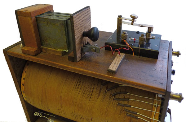
Popular Mechanics in 1918.The tuned circuit comprises two concentric
coils the outer of which is just under six inches in diameter and 9.5
inches long. There are 348 turns and 29 tappings on the outer coil
which are taken to the brass screws arranged in the upper semicircular
switch arrangement. I do not know the diameter or details of the inner
coil but the above mentioned article indicates that there are in total
more than 1000 turns. I guess therefore that the inner one has about
650 turns with tappings every 50 turns.There are two variable
capacitors, the one on the top made from zinc plates and pieces of
glass is about 450pF and the other (bottom left) made from two pieces
of brass tube is perhaps 160pF. The aforementioned article also
indicates that the "long distance receiving apparatus" was designed to
cover wavelengths from 7500metres down to 300 metres (40kHz-1MHz)
I have been experimenting trying to figure out how it should be
connected up. You will see that I have connected a germanium diode
across the crystal holder and as yet have not constructed a fixed
capacitor which was missing when I acquired what was a rather dirty and
corroded junk item. The connections between the coil tappings and the
switch studs have all been replaced with tinned copper wire. It was
also missing knobs on the switch sliders and the insulation on the
sliding tube was a sticky length of impregnated fabric tape.
I was puzzled by the arrangement of the two wipers on the top switch,
the shorter of which traverses about 12 of the tappings and the outer
can traverse all of them if lifted over the shorter one. This is not
possible with the design shown in the drawing above.
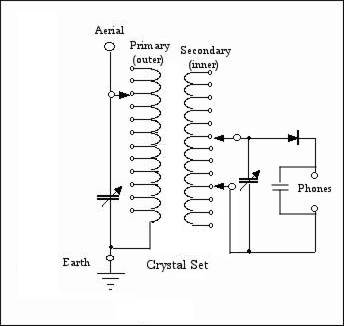
From one of the numerous diagrams I found on this very informative site http://www.crystalradio.net/ I now know that it was intended to be wired up as indicated in the diagram below with the tubular variable capacitor in the aerial circuit. On this site there is a useful calculator for determining coil inductances by inputting the number of turn and the diameter of the coil former. From this and my own calculations it would seem that the primary is about 8500 micro henries and the secondary about 25000 micro henries. A degree of variable coupling is accomplished by altering the number of secondary turns and their relative position with respect to the primary using the top two switch wipers.
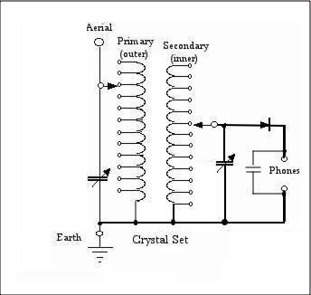
Andy Saunders in response to my query has kindly scanned a number of pages from his copy of "The Amateur Mechanic" and I have now amended the circuit diagram below to match that in the text. I see now that the double wipers should traverse the lower connections rather than the upper ones. I have yet to wire it up correctly and follow the instructions for setting it up. In due course I hope to add more information about this very early design.

The following table reproduced from the above mentioned article indicates the suggested switch positions for various wavelengths.
| metres |
Primary |
Secondary |
kHz |
| 600 |
2 |
1-2 |
500 |
| 900 |
3 |
1-3 |
333 |
| 1200 |
4-5 |
1-4 |
250 |
| 2000 |
5-6 |
1-5 |
150 |
| 2600 |
9-10 |
1-7 |
115 |
| 3500 |
15-16 |
1-8 |
86 |
| 4000 |
20-21 |
1-10 |
75 |
| 5600 |
28-30 | 1-13 * |
53 |
| 7200 |
25-26 |
1-13 * |
41.6 |
| * with secondary condenser | |||
I have found it useful when experimenting with this and other
crystal radios to connect a self powered loudspeaker in parallel with
the SG Brown headphones. see here. A slight
tap on one of the earpieces will switch the amplifier on.

