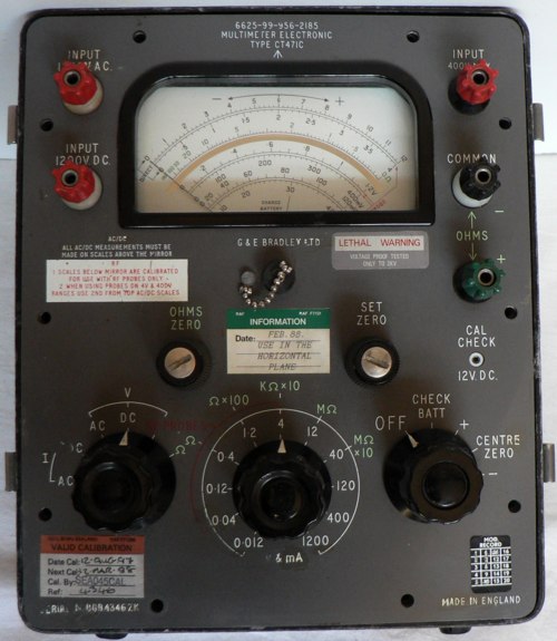
G+E Bradley Ltd. Multimeter Type CT471C meter
unit only. I saw this in the window of J Birkett's radio shop in
Lincoln, although incomplete I thought it worth Ł 2.50 so my son in law
bought it for me! Sadly as expected it did not work, though three new
1.5 volt cells showed at least that the meter movement was OK when
operated in the check battery mode.
Whilst researching for information on this instrument I found a model
CT471 for sale on eBay and bid successfully for it. This came with a
manual dated 11/68 which includes operating and calibration
instructions and a circuit diagram.
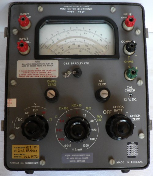
G+E Bradley Ltd. Multimeter Type CT471 complete with cover, leads, clips and probes (see pictures below)
This instrument did not work either, though with the help of the
diagrams I soon discovered that the final transistor of the AC
amplifier was short circuit.This and the two preceding it are CV8384
but are also marked Mullard OC170 (the 4 lead things that are prone to
fail). I replaced this with a PNP 2N2904 and 'Hey Presto' it was
possible to get readings on all ranges. By following the set up and
calibration instructions I have a meter that is reasonably accurate on
all the ranges I could verify.
The CT471C also had the same fault and it was noted that all three
CV8384/OC170 transistors had been replaced previously. Again I replaced
the currently faulty one with a 2N2904 and replaced a leaking
electrolytic capacitor. The instrument currently displays readings
which are consistently low on all ranges and therefore requires further
work when time permits.
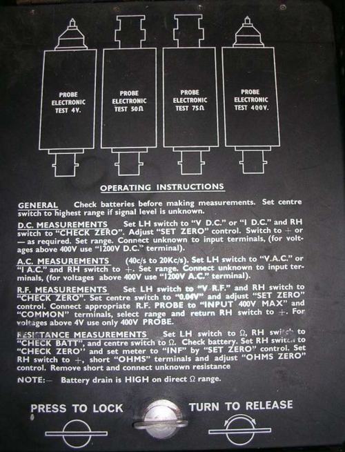
The lid of the instrument has a flap behind which are the RF probes and leads.
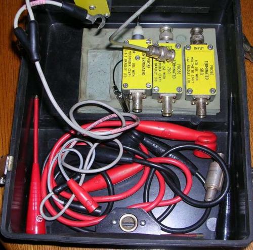
The RF probes and leads.
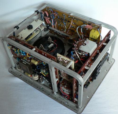
This is what is inside
To the left is the power supply board comprising 2.5 V
stabiliser, multivibrator switch and 20 Volt stabiliser.
On the right is the input attenuator and chopper circuitry.
The other printed circuit board at the top of this picture contains the
amplifier, phase detector and emitter followers.
As can be seen the circuitry is quite compact and complex. In total the
boards include:
21 transistors
120 resistors
37 capacitors
and 23 diodes
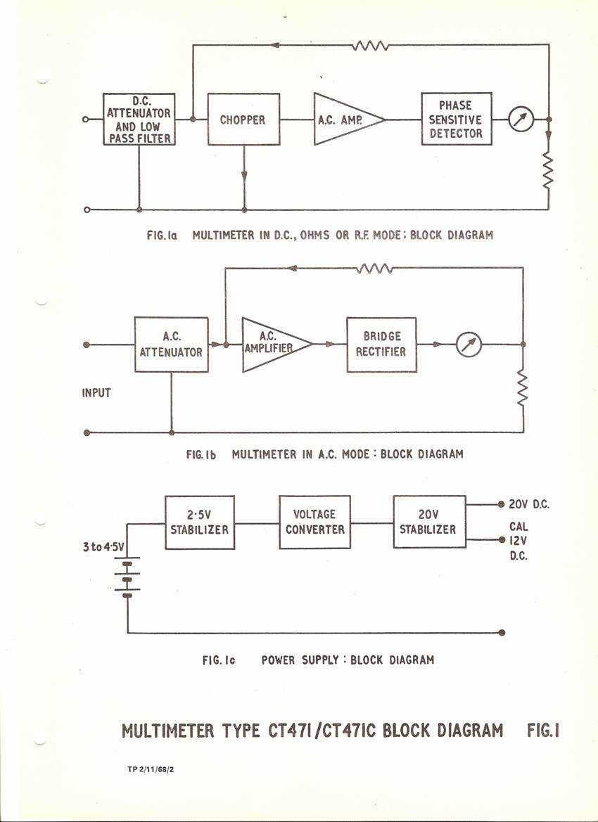
Schematic Diagrams
You can download a copy of the manual and circuits diagrams here: http://www.vmarsmanuals.co.uk/
Charles Brown was given two of these meters some years ago and recently decided to check them out. Both worked but one had a badly corroded battery compartment, the other a sticking meter movement. A quick swap produced one apparently excellent instrument. He found that it works happily with 3 x D Ni-Cad cells at 3.4 volts. He now has an almost complete set of spares, 3 boards with all components and most of the other bits, including switches, probes etc and the meter with a sticky movement, which is probably repairable. He has removed all from the cases to save space. Free for the postage and packaging to anyone who needs them. You can contact him at: chasbr744*btinternet.com.
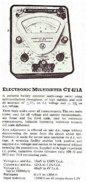
AVO also manufactured their own rather different version of this electronic multimeter the CT471A as this advertisement from 1968 shows:
I will add more information if there is sufficient interest.

