serial No. 58901
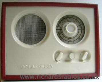
DOUBLE DECCA Valve Radio. This is a mains/battery set first introduced in this style in 1946 with octal based valves X14, Z14, HD14, N15 and metal rectifier. The radio shown and described here is a later model (possibly 1953) incorporating miniature B7G valves: 1R5, 1T4, 1S5, 3Q4 and metal rectifier. It is housed in a plywood case covered in an embossed "leatherette" type fabric, the front panel is of pressed aluminum sheet sprayed white. The set was designed to operate on AC or DC mains 100-120V, 200-220V,230-250V or a 90 Volt (Ever Ready B107) battery and a 7.5 Volt (Ever Ready "All Dry" 31) battery.
I have a schematic diagram(968 kB PDF file)(click here to see) for a "Double Decca ML" which applies to serial numbers 5000 onwards. However unlike this diagram my radio has Long Medium and Short wavebands as did the original model of 1946.
As far as I have been able to find out these are the variations:
Double Decca 46 had three circuit variations [ser nos. 5000-6000, ser nos. 7000-8000 and ser no 8000 onwards] The latter dating from 1948. Some sets had Osram valves others had Mullard or American valves]
Double Decca ML [ser 5000 onwards]
Double Decca MB5
Double Decca MB5A
Double Decca MB5B
Double Decca MB5C
The first two look much the same externally, the others are quite different.
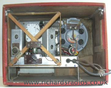
Rear view of radio showing the detachable frame aerial used on the long and medium wavebands.
I bought this little radio on Ebay, it looked fine in the pictures, and I was aware that one valve was missing so it did not cost a great deal. It has been sitting on a shelf for a long time as I found that although I had spares for three of the valves I did not have one for the missing output valve.Whilst waiting for delivery of a new N18 output valve I started to trace out the circuit using the two diagrams that I had (post war model 46) and the diagram mentioned above it was clear that several modifications had been made to the set. It soon became apparent that someone had discovered that the LT voltage was low when the set was operated from the mains and had therefore removed two shunt resistors which would have been across the filaments of the 1T4 and 1S5 and shunted the dropper resistor for the filament supply. The electrolytic capacitor (top right on chassis) was clearly a replacement and OK but the rectifier was beyond repair. The electrolytic capacitors were checked and proved to be OK. It was noted that the previous repairer had had an accident with a screwdriver and shorted the mains to the moving plates of the tuning capacitor thus causing them to touch the fixed ones in one particular position. This was easily rectified with a thin file rubbed between the vanes.
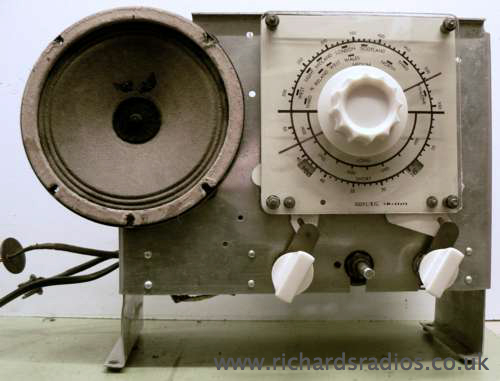
Front view of chassis showing the link mechanisms for operating the "mains/off/batt" and "L/M/S" indicator flags.
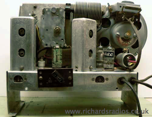
Rear view of radio without the frame aerial but with new output valve in place.
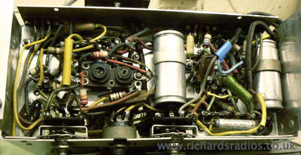
Underside of chassis as received.
Several capacitors had been replaced and a resistor wired in
parallel to boost the HT. Prior to operating the set on mains voltage I
adjusted my variable power supply to provide 7.5 volts and another to
provide about 90 volts. With these two connected the set produced
noise, the output stage and speaker were working but not for long. One
of the lugs on the valve base supplying the heater current to the 1S5
had corroded and was only making intermittent connection. As can be
seen from the jumble of components in this area I did not relish
replacing the holder. By carefully chipping away part of the base I was
able to solder a connection to the part still within the Bakelite base.
I also replaced the AF coupling capacitor to V3 and a filament
smoothing capacitor.
The set now worked well enough to tentatively operate it from a reduced
AC mains voltage. This confirmed that the metal rectifier had to be
replaced with a silicon diode (3A 600 Volt) and a series resistor of
180 Ohms. Although The set now worked on all 3 wavebands the hum from
the loudspeaker was unbearable. It was indeed a puzzle only resolved
when I poked the large capacitor on the right in the view above. This
is a twin unit 16 +16 mFd and the clip securing it to the chassis was
not effectively making an electrical connection. The HT smoothing
resistor was being shunted by the two capacitors effectively being in
series.
I decided to remove the rectifier and replace it with a tag strip on
which I mounted the diode and wire-wound resistor. The set now works
quite well and considerably better with a short indoor aerial. Although
this radio looks good on the outside it is a pity that the designers
did not give a little more attention to the accessibility of the
internal components.
Note this is an AC/DC radio and one side of the mains is directly
connected to the chassis and all metalwork visible when the back is
removed.The blue conductor in the mains lead MUST be connected to the
neutral pin of the mains plug.It is also important to ensure that the
patches covering the chassis fixing screws remain intact and are
replaced after any repair.
History The Decca Company, which was first established before the First World War, manufacturing gramophones and by 1929 was producing gramophone records under the Decca label. Within years, it was the second largest record label in the world but by the late 1970's the record side of the business was not doing well and was acquired by Polygram in January 1980.Decca branched out from making gramophones and amplifiers to produce radios and subsequently Television receivers. During the Second World War, the company developed the Decca Navigation System, which was first used on D-Day to assist the Allied minesweepers and troop ships in navigating to the beaches of Normandy.

