Introduction
The model EC10 receiver was one of
Eddystone's very early solid state communications receivers, which was
first introduced in 1963. It employed ten Germanium transistors (OC171
X7 OC83 X3) and
three diodes. It is compact, well built and intended for operation from
its own internal battery supply or from a mains-operated power supply
unit. Five ranges give continuous coverage from 550 kHz to 30 MHz, and
included are the medium wave broadcast band, the marine band from 1500
kHz to 3000 kHz, all the short wave broadcast bands and six amateur
bands from 160 metres to 10 metres.
The receiver accepts normal AM signals and CW telegraphy, a special
filter being provided to increase selectivity in the latter mode.
Although not designed for single sideband operation, signals in this
mode can be received by appropriate setting of the BFO for carrier
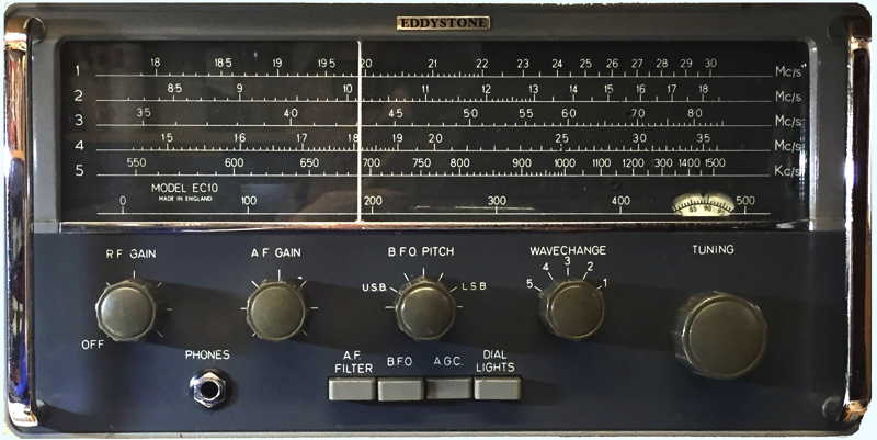
insertion. Features standard to all Eddystone receivers are
incorporated. The flywheel-loaded tuning knob controls a finely
engineered gear drive with a reduction ratio of 110 to 1, resulting in
smooth precise tuning. The main scales occupy a length of nine inches
and are clearly marked directly in frequency to an accuracy of
calibration within 1%. Tuning to a given frequency is therefore
relatively easy and an auxiliary logging scale permits dial settings of
preferred stations to be recorded for future reference.
Alternative aerial sockets are provided allowing the use of a really
good aerial system where circumstances permit, or of a short rod or
wire where nothing better can be arranged. An internal speaker is
fitted and a telephone headset can be used where preferred.
Power is derived from six U2 type cells housed in a separate detachable
compartment. Current drain and hence battery life is dependent on the
audio output. For long life, it is recommended that the HP2 heavy duty
type of cell be flitted.
Sridharan
Jayaraman who worked in a Police wireless Dept where most of
their wireless sets were designed with these transistors. Provided the
following:
Since the OC171, AF114, AF115 and AF117 were prone to grow
dendrite inside and short electrodes we were replacing them with
AF124 for AF114 or AF115
AF127 for AF115 or OC171
He noted that even old stocks sitting on shelf can grow dendrite and go
useless.
I have had this radio for nearly 20 years
and have switched it on
only very rarely. Recently (2020) on powering it up I discovered that a
couple of the OC171s were playing up resulting in great crackles and
eventual near silence. I have now snipped all the transistor screen
leads and it now plays daily in my workshop.
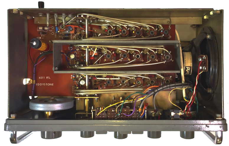
Underside RF and oscillator stages
Upper board IF BFO and output stages
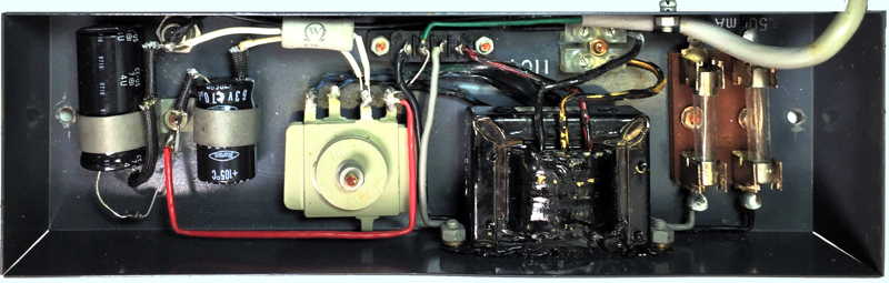
Power supply Cat No.924 delivers 9 Volts at up to 200 mA
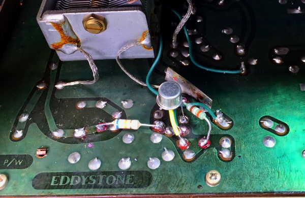
Amended First stage RF amplifier as suggested Chris Arthur VK3CAE
Replacing
the 1st RF Amp (TR-1) with a Silicon Transistor
Chris
Arthur VK3CAE tried an experimental modification as a temporary
replacement for the dead OC171 connected in Common Base configuration.
This was to make best use of the OC171's somewhat limited Hfe
characteristic which falls off at higher frequencies. In using a
Silicon transistor over a Germanium device there will be an improvement
in signal to noise but the DC conditions will be a little different. He
used a 2N2907 PNP Si device and changed the bias resistors as follows:
Resistor R1 (68KΩ) with a 33KΩ. Resistor R3 (470Ω) with a 220Ω.
I used a 2N2907 as suggested and shunted
the existing resistors with a 68KΩ and a 470Ω rather than removing them
from the board to achieve the same result.


