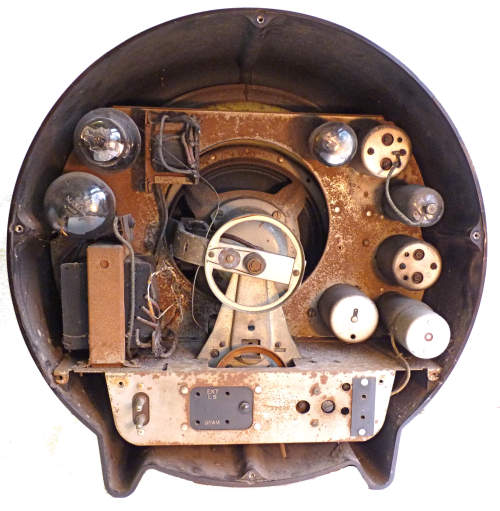
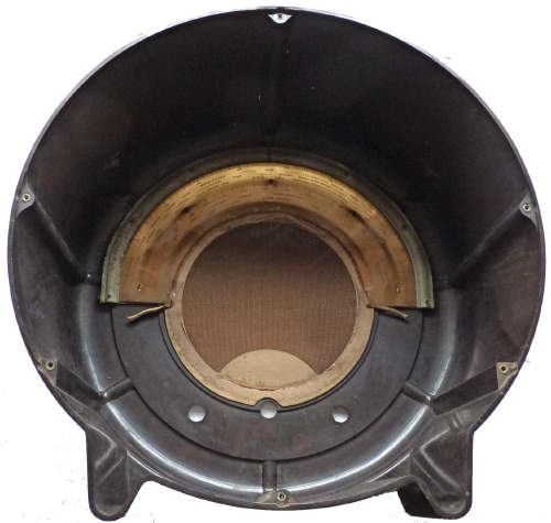
These are views of the radio as received. My heart sank when I removed the back cover and saw the state of the interior.
Serial number 32000
These are views of the radio as received. My heart sank when I removed the back cover and saw the state of the interior.
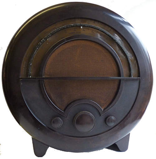
This valve radio was given to me by my family as a joint birthday present in 2013. The interior was in a poor condition when received but the case was nearly perfect, though needing a light clean and polish. A cursory inspection convinced me that it would be foolish to energise it until I had had a good look behind and underneath the chassis. The first task would be to remove the knobs so that it could be slipped out. This proved to be a stumbling block, the large central knob and that on the right hand side came away easily but the two small ones on the front fiercely resisted all my efforts. Eventually after several days waiting for penetrating oil fail to work wonders, I resorted to drilling out around the grub screws. I had found by searching the internet that there is a firm that make replica knobs so I reasoned that there was a fall back solution if needed. The knobs surrendered to this drastic action and the resulting cavities were filled with "Milliput" two part epoxy putty (see pictures below). The serrations were accomplished by rolling the knobs together and when completely hard they were drilled and tapped to take new 6BA grub screws. Two coatings of brown "Humbrol" enamel model paint completed the job.
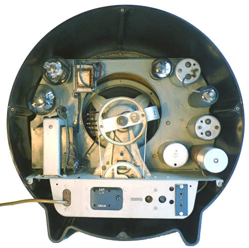
These are views of the chassis as received. Power is supplied to the radio by a female plug which would mate up with the two pins protruding from the rear of the chassis.
Having removed the case I then turned my attention to the radio itself. Apart from the dirt and dust on the top of the chassis it was apparent that the dial cord had broken, the electrolytic capacitors were in need of replacement as were most of the others. The loudspeaker which had been holed was inexpertly repaired and half the felt around the its rim was missing. Reluctantly I decided that wholesale replacement of the electrolytic and paper capacitors seemed to be in order. It was also noted that some of the rubber insulation on the wiring had become very brittle and in a few places had come away.
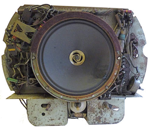
The valves were then removed and cleaned and the bulk of the dust removed from the chassis. The energised loud speaker was checked for continuity and removed after carefully making a note of the connections. The frame of the latter was de-rusted and the previous repair to the cone was removed and re-done. Using light grey gloss paint mixed with a few drops of yellow and blue oil colours to get an approximate match I thinly painted the exposed areas of the frame and magnet. On the underside of the chassis it was observed that the two cardboard cased electrolytic capacitors were not original and a quick test revealed that they were no longer functional.The tubular one made by RadioSpares has a date code indicating that it was made in 1942 and the rectangular one made by British Insulated Ltd only contained two capacitors rather than the three of the original. I decided to keep the latter and to replace the contents with modern equivalents. Immersing it in boiling water melted the wax coating and that used to fill the interior sufficiently for the contents to be readily removed. After drying the cardboard casing was given a coat of shellac varnish before re-stuffing with two 8 mFd and one 4.7 mFd capacitors.
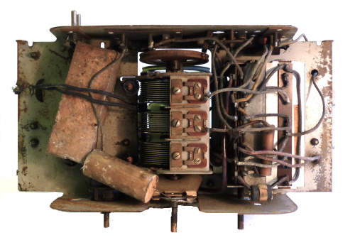
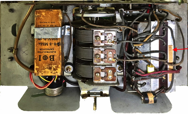
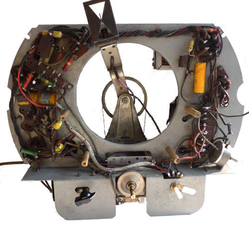
Underside of the chassis showing the capacitors that were wired in as replacements sometime during the early 1940s and the second after cleaning and the fitting of new capacitors in original cardboard housing. The date of manufacture 28 July 1935 has been stamped on a piece of self adhesive tape attached to the wavechange coil assembly [indicated by he arrow]
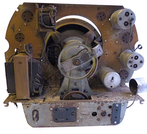
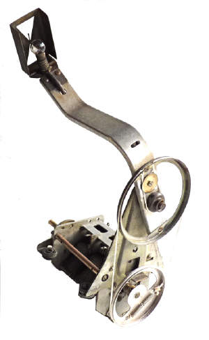
The three gang tuning capacitor was was very dirty, the slow motion drive needed cleaning, the rubber mounts had perished and the drive wheel for the dial cord was in need of de-rusting. I removed the whole assembly, used a "Dremel" tool with a wire brush attachment to remove the loose rust and then washed it in hot water and detergent. An old tooth brush and a pipe cleaner helped getting into awkward corners. The lower dial drive wheel was treated with rust remover and after washing and drying was covered with a thin coating of "Goldfinger" silver rub-on metallic paste. Re-stringing requires 33 inches of dial cord and was reasonably straight forward, though my cord was a little larger in diameter I should have allowed a little more. The four rubber mounts were replaced with rubber grommets. The large ones I had to hand fitted nicely but I had to insert a smaller one inside each and find four larger washers to refit the assembly satisfactorily back in place. However, before doing so I cleaned the underside of the chassis and applied switch cleaner to the wave-change switch by slipping a small piece of card backwards and forwards between the closed contacts.
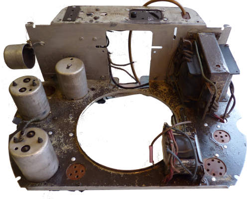
The chassis during the cleaning process. The surface with the valve holders has been coated with rust remover, prior to washing, drying and painting. The tuning assembly ready for installation is on the right.
I thinly painted the exposed areas of the chassis with the previously made paint mixture using a long handled artist's brush to get into the awkward corners. After a day or two I returned to the set gradually replacing each capacitor in turn, I had hoped to slide my replacements inside the insulated tubes which held the originals but they were not quite small enough to fit. I removed the hardened perished rubber from several wires and re-sleeved them, the screened wires to the volume control were replaced completely as they were perilously close to shorting out to earth. The picture below shows the parts that have been replaced.
When I energised the set without the rectifier in place but feeding the HT from an external variable DC supply nothing happened. There was complete silence and no glowing valve heaters or dial lamp. I checked the fuses the dropper resistor and the in-line RF filter chokes, everything is in order, but I found that the double pole switch on the rear of the volume control seemed to be stuck in the open position. When this was taken apart two pieces of broken spring fell out. I had a 1 megohm log potentiometer with a double pole switch and with some ingenuity I managed to exchange the track from a similarly sized potentiometer for one of 500K which was the nearest I had to the 250K original. I removed the original mains input pins and permanently wired the radio up with a three core lead and earthed the chassis.
Now feeling optimistic, yet cautious, I inserted the rectifier, fed the set via my variable transformer and gradually increased the voltage. The dial lamp and heaters glowed, but again there was complete silence from the loudspeaker. I soon found that the primary of the output transformer was open circuit. Fortunately I had a multi-tapped replacement which had the same fixing centres. I used the 45/1 tapping. When this was connected up noise came from the speaker and when an aerial was plugged in I found that it worked fairly well on both wavebands. Whilst the set was left working merrily on the bench top I turned my attention to the Bakelite case.
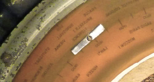
The first job was to remove the semicircular (and semi-transparent) scale together with the curved central metal bar which is attached to the latter by small screws. The loudspeaker grille cloth and surrounding cardboard was then gently prised away from the case so that the Bakelite case could be washed with warm water and detergent without spoiling anything.
Over the years the scale had shrunk and warped. Where it had been constrained by the fixing screws the holes had elongated, as can be seen from the first picture on this page. The curved metal bar had corroded and its brown painted surface was in poor condition. The paint that remained was removed with paint stripper and the bare metal smoothed with a file and wet and dry carborundum paper. Two coats of the brown "Humbrol" were then applied. After washing the scale I doused it in hot water and attempted to flatten it by placing it whilst still warm under a weighted board to cool. after doing this a couple of times it was clear that I would need to ease the holes and improve the method of clamping the scale to the bar. The original washers were discarded and thin rectangular steel strips were made and used in their place (see picture)
As the loudspeaker grille cloth was very dirty and fragile and did not respond well to washing it was discarded and replaced with a piece of similar colour to that of the unexposed part of the original.
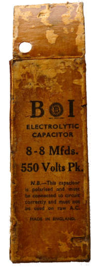
One of the new pieces made to restrain the scale and on the right a picture showing the cardboard capacitor casing prior to the insertion of replacement capacitors.
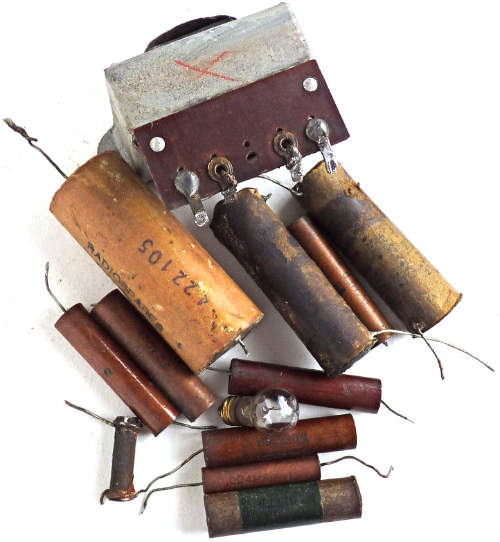
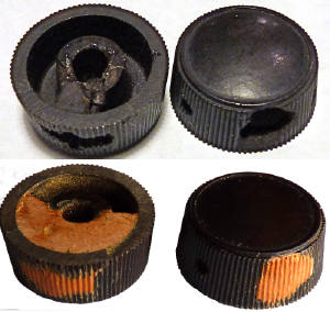
These are the faulty components removed from the radio and on the right a picture showing how the knobs were repaired.
The date code on the "RadioSpares" capacitor which is clearly
visible indicates that it was made in 1942 and several of the other
capacitors have date codes for June 1935. The base of one of the valves
is stamped with a number that indicates that it was made in 1942. Apart
from the above mentioned items no other repairs appear to have been
made, though it was noted that some of the back panel and chassis
fixing
screws were missing. The speaker cone must have been damaged and
repaired whilst the set was outside the case. The date of manufacture
28 July 1935 has been stamped on a piece of self adhesive tape attached
to the wavechange coil assembly [indicated by he arrow]
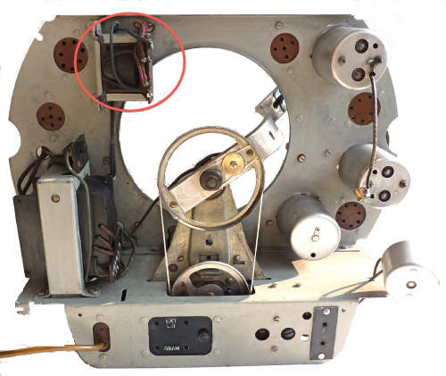
Front an back views of the chassis after cleaning and restoration. (circled is the faulty output transformer)
After removal I checked the output transformer, hoping that perhaps there might be a poor connection at one end or the other of the primary. When I took it apart and removed the windings I found that the inner layers had been hot and fused to the cardboard former and I concluded that this must have been where the open circuit was located. Such a failures can be caused by excess anode current being drawn by the output valve because of a positive voltage appearing on its grid. This in turn is usually due to the coupling capacitor from the preceding stage having a poor insulation resistance and leaking current from the HT line to the grid.
The inside of the casing before cleaning and adjusting the scale and a picture of the interior after cleaning and restoration.
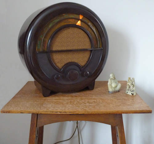
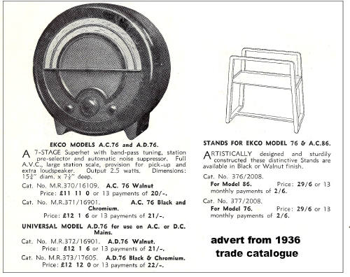
The radio now working and on display and an advert from 1936 which indicates the list price as � 11.55, the trade price at the time was � 8.09. This would have been over three weeks wages for many people back then.
For several years the radio has been
switched on now and again but lately [2020] it ceased to work on both
wavebands so the interior was revisited and the problem was found to be
related to the switch contacts. Whilst trying to sort out this problem
I discovered that the switch and coil numbering on the Manufacturers
and the Trader service sheets are completely reversed. I also noted
something that I had not when first working on the set, the date of
manufacture 28 July 1935 stamped on a tape stuck to the coil assembly.
Whilst the chassis was out of the case I took the opportunity to
replace both cathode bypass electrolytics.

