serial number 12151
EKCO
MODEL Ul22 is a five-valve, including rectifier, transportable
super heterodyne receiver covering the Medium and Long wave bands. EK Cole Southend UK 1950/1 Original
cost Ł12 1s 7d plus purchase tax. It
is contained in a thermo-plastics cabinet with two built-in frame
aerials,
provision being made for the use of an external aerial in areas of low
field strength.
MAINS SUPPLY: 200, 25O volts DC or AC 25-100 Hz.
NOTE. An additional mains tapping screw can be provided to enable the
receiver to operate from 115 volts mains. An additional screw is
inserted in the 115V tapping (covered by plastic tape) of the mains
adjustment panel, leaving the existing screw in the 200 /
220V tapping.
CONSUMPTION: 153.5 mA with 240 volts A.C. input, 37 watts. 43.5 mA with
222.5 volts D.C. input, 32 watts
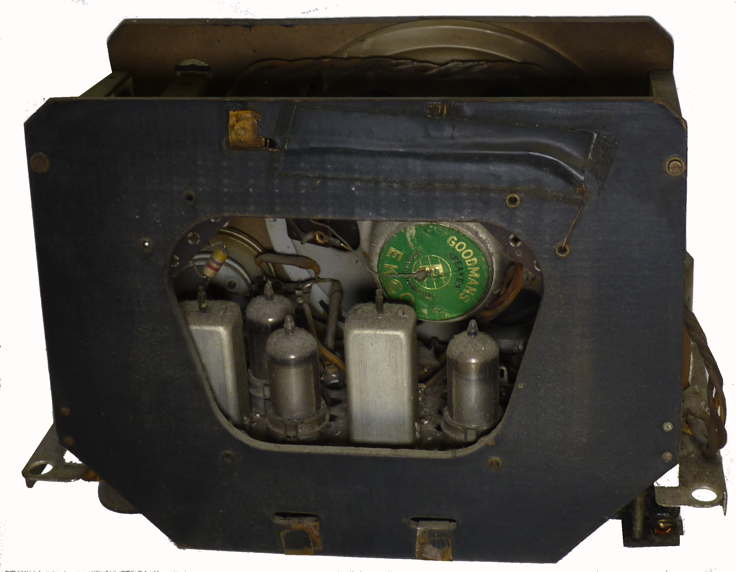
VALVES
VI-UCH42 Frequency changer.
V2-UF4| IF amplifier.
V3-UBC-41 Demodulator AVC,LF amplifier.
V4-UL4I L.F., amplifier.
V5-UY4I Halfwave Rectifier
All valves are Mullard and have BBA bases
PILOT LAMPS 6 volts 60 m.a. M.E.S
LOUDSPEAKER IMPEDANCE: 3 ohms at 400 c.p.s.
INTERMEDIATE FREQUENCY: 470 KHz.
FREQUENCY COVERAGE: MW 560 to 532 kHz LW 311 to 142 KHz.
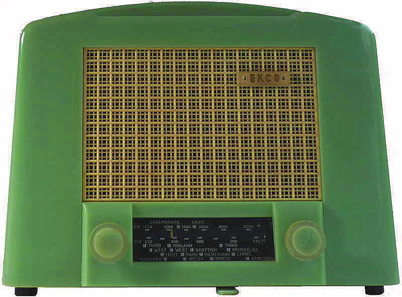
This was Ekco's first portable radio housed in a polystyrene
case. This is a style often referred to as a "toaster radio" Murphy KB
and others made AC/DC sets of this basic shape designed for portability
and destined predominantly for use in the kitchen as a second radio.
The term is generally assumed to be because of the shape, though cynics
say that it is because of the heat dissipated by the dropper resistor
and the valves in such a confined volume. Like others of this type it
incorporated the 'tea cosy ' concept i.e. the case was placed down over
the
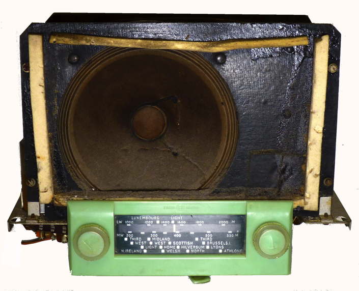
chassis which was secured from the underside. It was designed by Chief of Industrial
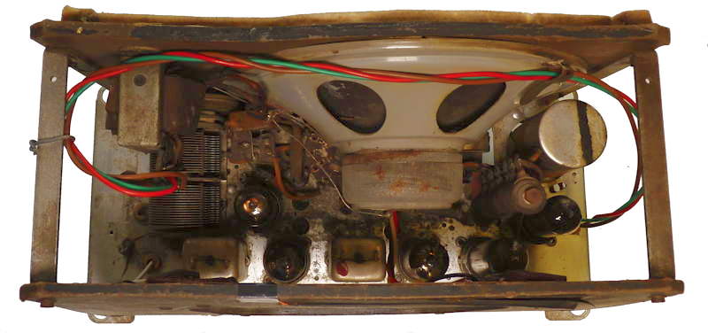
Design J.K.White in 1950/1. The design is such that it can be worked
on without the need for additional support as the frame aerial is much
the same size as the speaker baffle.
CHASSIS REMOVAL Lay receiver flat, knobs
uppermost, then remove the four rubber feet and slide base cover along
the mains cord. Remove the four corner hexagonal pillars and the
chassis is then free to be withdrawn from the cabinet. To remove the
escutcheon, pull off the two knobs and the plastic washers beneath
them, Unscrew the two screws now exposed. With the chassis and
escutcheon removed, care must be taken to prevent undue pressure on the
wave-change lever which will snap if grossly mishandled.
DANGER FROM SHOCK: As is usual with AC/DC receivers, the chassis is
connected to the mains, and care must be taken when handling a “ live ”
chassis. Ensure that chassis is connected to the earth side of AC mains.
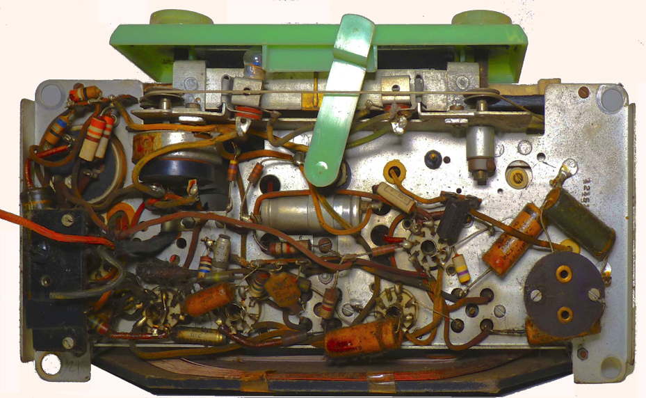
This radio was given to me by my son and daughter in law as a Christmas present in 2014. It came without a mains lead and the chassis was caked with years of dust. After dusting the chassis I found that the one side of the double pole on/off switch was open circuit and as this was an integral part of the volume control I decided to alter the wiring to incorporate a new mains lead and use the functioning contact to switch the live side of the mains. However before connecting it up checked the continuity of the speaker, its transformer, the valve heater chain and the dropper resistor. All seemed OK so I then removed the valves and applied a gradually increasing DC voltage directly to the smoothing capacitors to reform them. The valve pins were cleaned treated with switch cleaner as were the valve bases and the wave change switch. When switched on and connected to the mains I soon had to switch off as the capacitor across the mains started to complain and eject its intestines. when this was replaced the set produced stations on both long and medium wave but with a great amount of background noise. By using a 0.1mFd capacitor connected to chassis and touching on various parts of the circuit to find out where the source of the noise could quieted I discovered that the holder for the frequency changer valve was making a poor connection. A small watchmakers screwdriver was used to bend all the contacts and this solved the problem. As the dial lamp fitted was open circuit and the other absent I temporarily wired up two white LEDs with dropping resistors to take their place.
Although the radio was functioning it was
clear that the wiring to the loudspeaker transformer would need
replacing as the rubber insulation had perished. The electrolytic
cathode bypass capacitor was replaced as was the capacitor across the
live and neutral mains supply.
I revisited the radio again 4 years
later to insert new dial lamps which should be 6V 60 mA with two
100mA that I had to see if they would glow sufficiently. They did what
I thought was a good enough job. so I set out to complete the work that
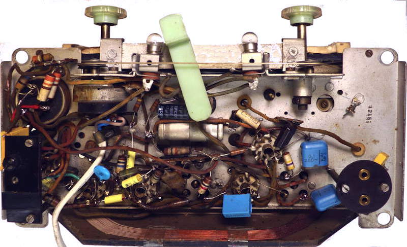
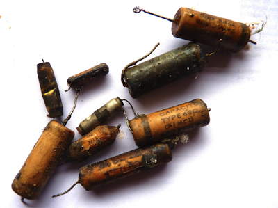
I had started previously. Knowing the problems with wax coated
capacitors in radios of this age, I disconnected a couple and found
that they had serious leakage when tested with an insulation tester. In
the end I replaced all of them with new and salvaged ones (the yellow
and blue items on the second picture below)