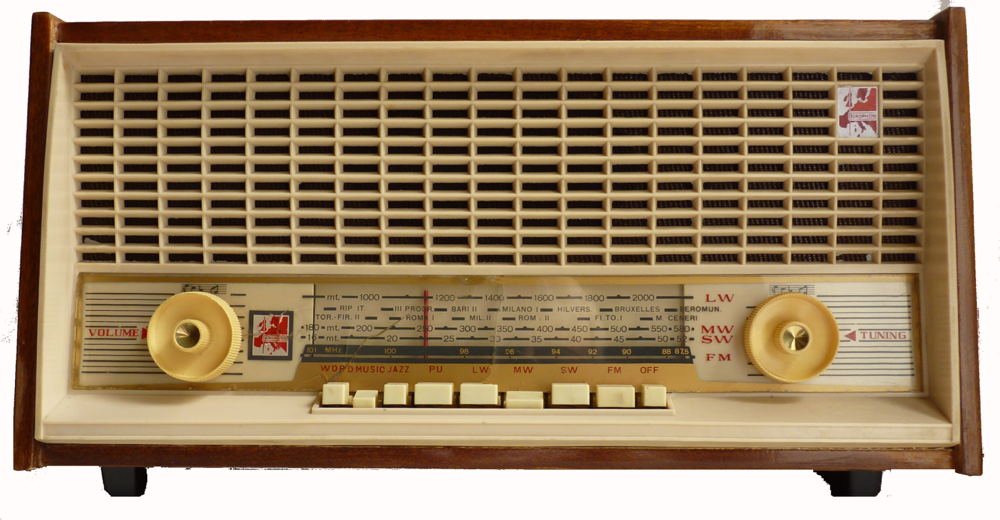
Europhon tube radio Long, medium, short and VHF waveband superhet table radio with pushbutton selection, manufactured by Europhon in Italy. As can be seen from the pictures the radio has seen better days, the tuning scale had been broken in three places and glued back together and one of the knobs was broken but when first energised worked on all wavebands. It was put to one side for over a year as I was unable to find a schematic diagram until an internet search proved successful.
This model one of several radios made by Europhon in Milan which are electronically identical. ES60 one loudspeaker, voltage adjustment external. ES61 one loudspeaker, voltage adjustment internal. ES60-200 two loudspeakers, voltage adjustment internal. As indicated by the model numbers they were made in 1960 and 1961 respectively.
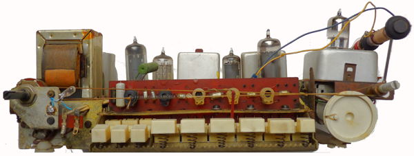
This is an AC only radio which has a live chassis, but utilises an auto transformer rather than a dropper resistor to provide the voltages for the HT and heaters. The valve line up: 6BQ7A [fm] 6AJ8, 6BA6, 6T8, 3506, 35A3. The set as received was equipped as follows:6BQ7A [fm], ECH81, EF88,6T8, 35D5, 35A3 The intermediate frequencies are 470kHz and 10.7MHz.
This is one of a number of radios which belonged to the late Ron Griffiths which were given to me by his widow in 2013. Ron was was an engineer, working for himself and making parts for other firms. He made some items for the Pastorelli firm - brass cases for surveying equipment that is used in tropical climates - and also brass parts for Cambridge Instruments.
A previous owner had replaced the main
electrolytic capacitor and added connector blocks for the mains lead,
loudspeaker connections and added sockets for aerial and earth. The
green high wattage resistor to the right of the transformer was clearly
a replacement as was the wire ended dial lamp. I replaced the two
cathode bypass electrolytic capacitors and used switch cleaner on all
the valve bases, lightly cleaned the chassis, replaced the mains cable
and made a paper logo to cover the opening on the top right of the
fascia. I guess the same cabinet was also used for other models which
had a tuning indicator.
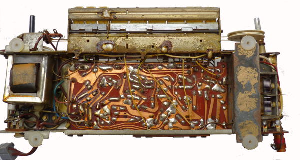
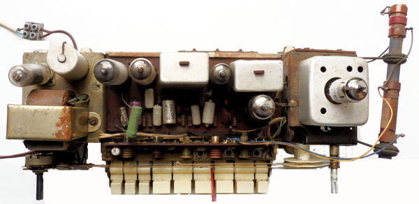
The loudspeaker transformer is mounted
below the power supply section. Note the design weakness; how the
tension of the tuning mechanism causes the right hand section to be
pulled out of line. The chassis is held in place by four screws which
engage with the four plastic inserts visible here, but note that the
knobs and the tuning scale plate must be removed and the chassis tilted
to get it out of the casing.