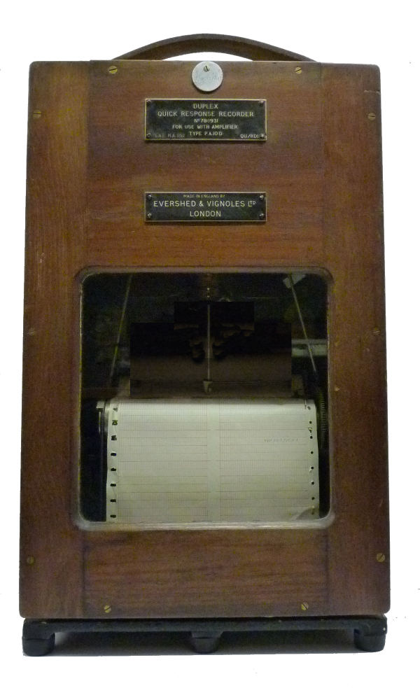
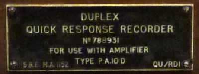
Serial No. 788931
Evershed and Vignoles Quick Response Recorder QU/RD1 in wooden case, with glass front. Working. Date perhaps 1940-45?. Evershed and Vignoles ltd, Acton lane, Chiswick, London W4 UK.
This is one of many instruments collected by Jack Davidson C Eng FIEE which I have been given by Dr Graham Winbolt. Fortunately it came with an instruction manual for a later model [QU RD 15J]. This was sent to Mr Kubale [one of the directors of AEI-GRS] in 1965 and included an amplifier diagram dated 1948. He or one of his assistants spent some time trying to puzzle out the connections to the multi way socket and produced a pencil sketch from which I was able see how it was intended to work. Incidentally the sketch indicates that the recorder was made by the Naval division of Evershed and Vignoles. The reference on the label [SRE MA 1152] might support this as the SRE could well refer to the Admiralty Signal Research department.
GENERAL DESCRIPTION
This instrument has two identical channels each essentially a D.C.
recording voltmeter with a rapid response and negligible pen to paper
friction errors.
The complete equipment consists of:-
a). The recorder unit which contains the two recording pens
with their associated movements and resetting potentiometers. A
solenoid operated time marker, and a chart driving mechanism driven by
a 20 Volt DC motor with centrifugal governor are included.
b). The Amplifier unit which contains a two identical D.C.
amplifiers.
c). A separate power pack.
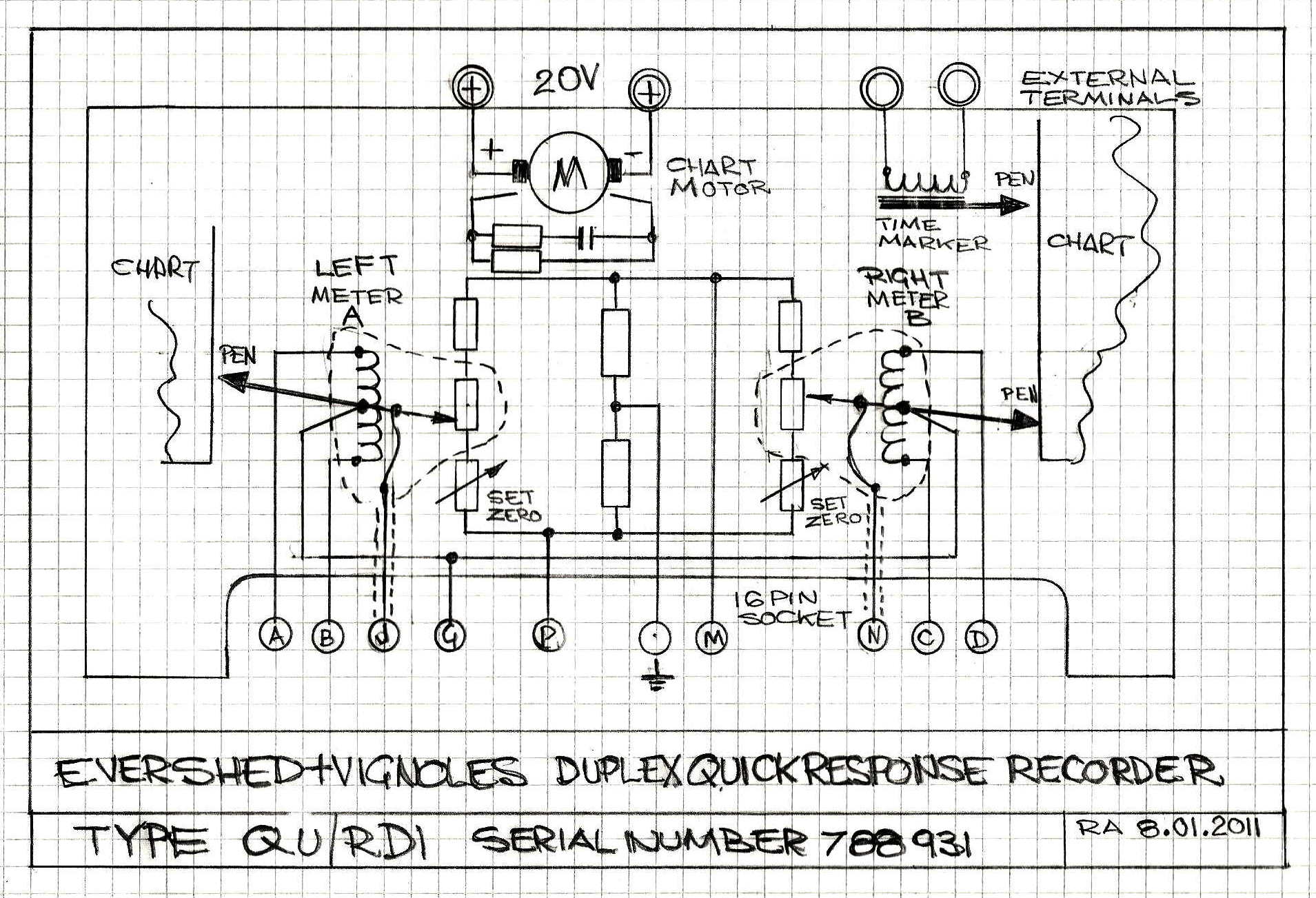
With the help of the documentation mentioned above I have produced a schematic diagram and established that the recorder could potentially work if one had the associated power pack and amplifier.
DETAILED DESCRIPTION
The recorder is servo operated, the input being compared with a voltage
fed back from a resetting potentiometer actuated by the pen arm. The
magnitude of the resetting voltage is determined by the position of the
pen. The difference voltage, or error, is amplified to drive the pen
movement which sets the pen in such a position that the resetting
voltage is equal and opposite to the input voltage.
Each recorder movement consists of a centre tapped moving coil attached to a specially braced pen arm assembly. The moving coil is pivoted in the field of a strong permanent magnet. To the top of the pen arm is attached a spear contact which bears on the resetting potentiometer. Each potentiometer is fed through a balanced resistor network from a neon stabilised D.C. supply derived from the power pack. The voltage can be preset to give the desired sensitivity by a variable resistor.
Each moving coil is connected in the cathode circuits of the two output valves of each three stage D.C amplifier. Valves: 12AX7, 12AX7, 6BW6 and 6BW6.
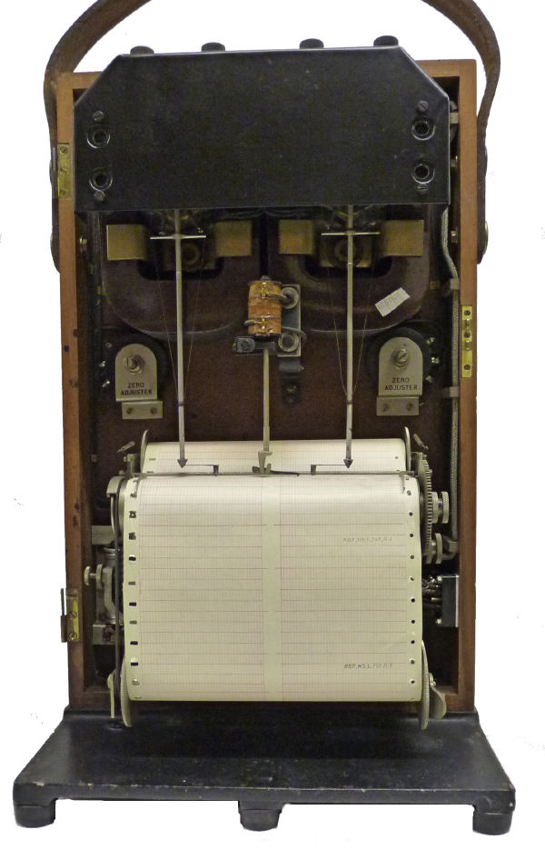
Inside the instrument.
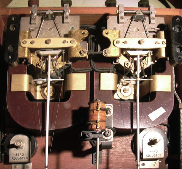
Two identical moving coil pen drives and feedback potentiometers.
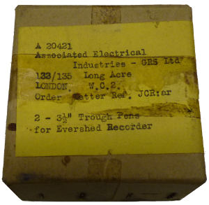
This box has two spare pens from 1965 .

