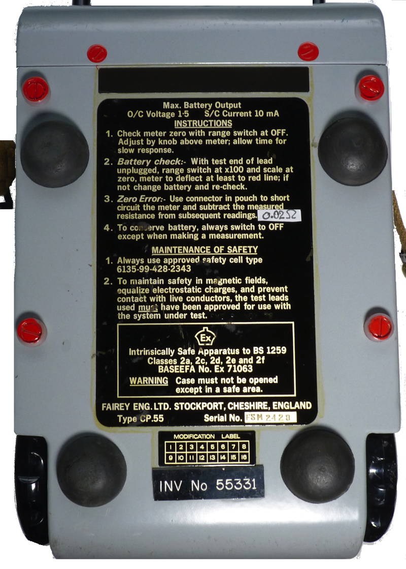
Fairey engineering ltd. Safety Ohmmeter Type CP55. This is one of a number of instruments given to me by Alan Honeyball used to work for an ICI manufacturing plant which did have a very well equipped Instrument department until they were down sizing and he couldn't bare to see some of the equipment thrown away, so he rescued some items, and it was his intention to keep these as items of art but he now felt they needed a better home. He added,"Hopefully I can spread some good will within the community of vintage electrics"
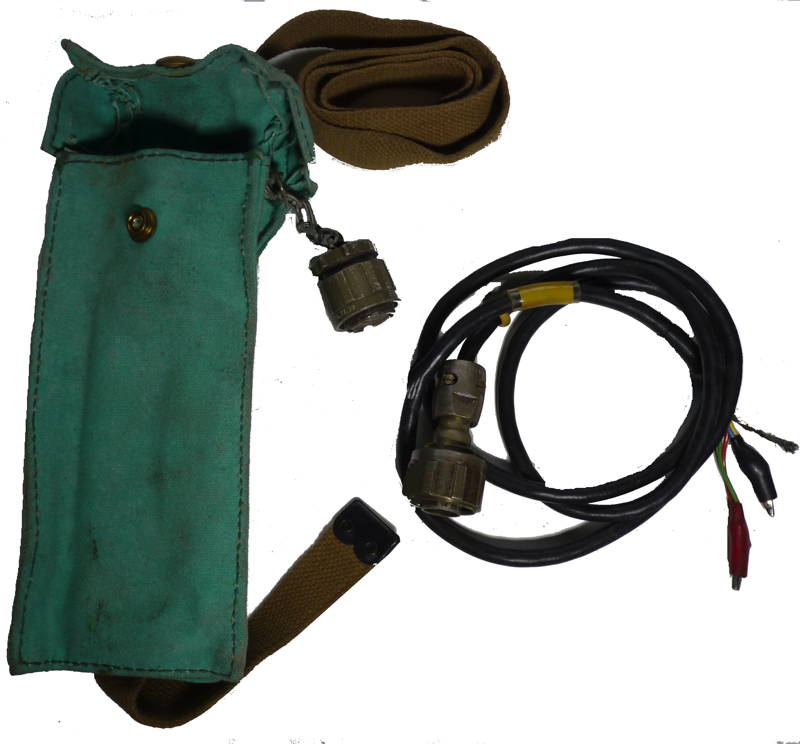
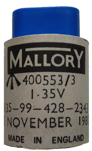
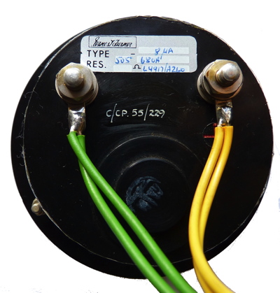
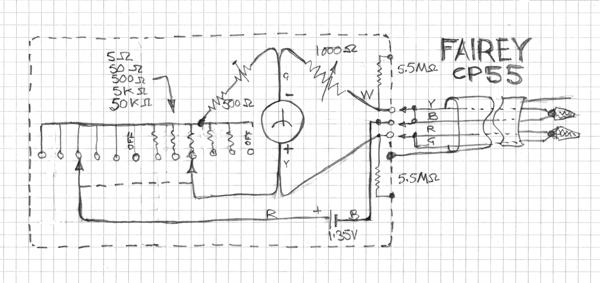
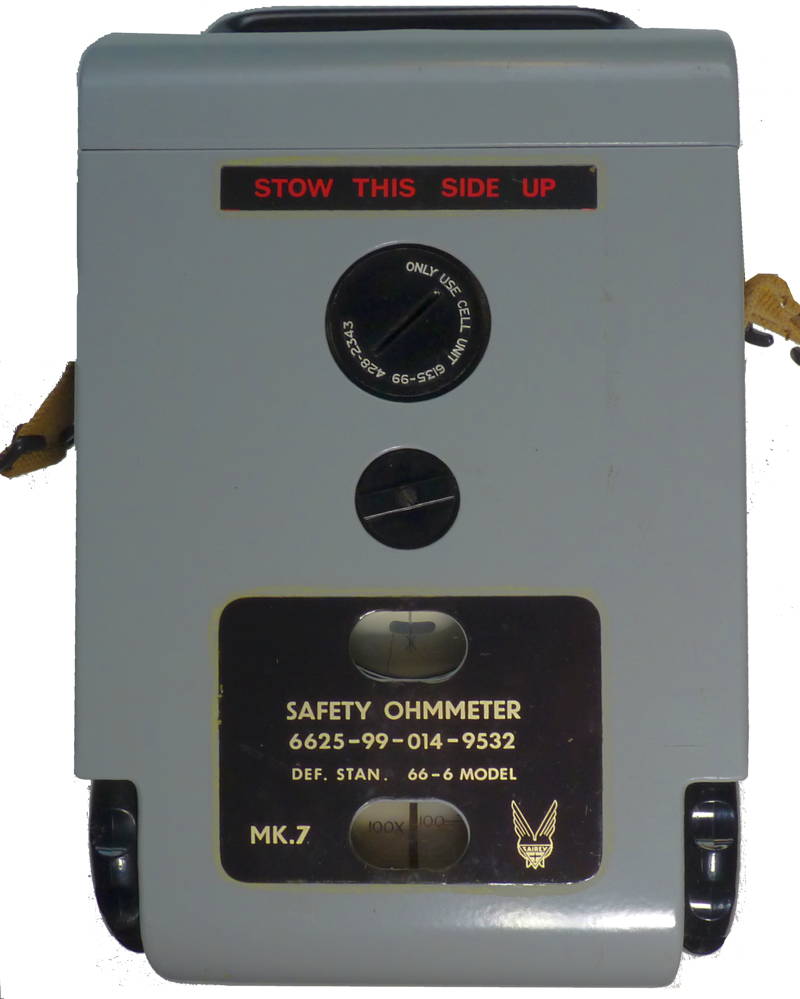
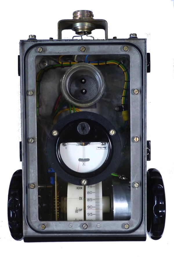
This is a conventional resistance bridge housed in a die cast metal case with a substantial clear 'perspex' screwed down cover on which the meter and compartment for the 1.35 Volt cell are mounted. This in turn is contained in the sheet metal outer casing which is electrically isolated from the internal metalwork. Connections to the item to be measured is via a calibrated four core screened cable terminated with 'crocodile' clips. The connections in the plug and socket for the latter ensure that the cell is disconnected when the cable is removed. The range switch (on the left in the above pictures) is used to alter the balance value indicated on the right hand indicator which forms part of a variable resistor. The five range instrument can measure from one tenth to one hundred times of the indicated balance indication.