Serial number F/18305
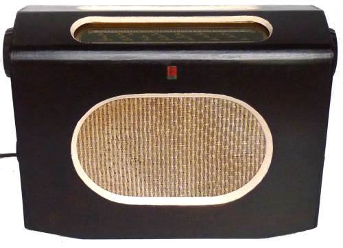
Ferranti Model 525 two waveband table radio - MW
(190m-570m), LW (1000m-2000m) It operates on a 200-250 Volt 40-100 Hz
AC/DC supply and consumes 50 Watts at 230 Volts AC. The valve line-up -
UCH42, UF41, UBC41, UL41, UY41. One of the electrolytic capacitors is
dated Jan 1952. When first produced it cost Ł 17.17s. UK 1952/3
Ferranti Models 515,525 and 545 are electrically similar, the 515 does
not have aerial an earth sockets.
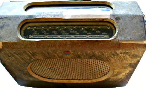
This one was in a sorry state when I purchased it on eBay, though when I energised it programmes were heard on both wavebands though the output was very distorted. The inside was relatively clean and only really needed a dusting. Somebody had previously tried to get inside and only succeeded in removing the wooden base, the correct way of accessing the works by removing the knobs must have proved too difficult.
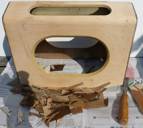
When I received it, the cabinet was in a grubby condition and the lacquer had crazed and much of the veneer was missing or peeled off. The first problem was to remove the push fit knobs which stubbornly refused to budge so that I could remove the chassis. I fashioned two wooden levers which I used to gently ease them off [shown on RH side of the picture above].The veneer came way very easily with the aid of a Stanley knife blade to reveal a smooth but much lighter continuous under layer which was then sanded and given two coats of stain [Ronseal and Sadolin]. The sides were treated with varnish remover and given a couple of coats of Danish oil.
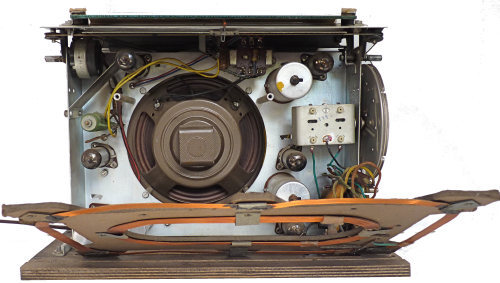
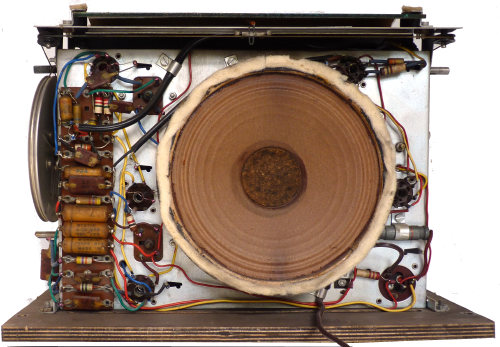
A fair quantity of dust was removed, wires on which the rubber insulation had perished were replaced and switch cleaner applied to the wave change switch wafers and the volume control. The dial lamp was open circuit but as I had no suitable replacement I constructed a stop gap using LEDs and a diode. The output valve was found to have low emission and an internal short and the capacitor on the grid to the output valve was causing the grid to become positive. These were changed as was the capacitor between the earth connection and the chassis. The dial lamp and some of the valves may have been replaced in the past, but as far as I could tell all the other components are as originally fitted.
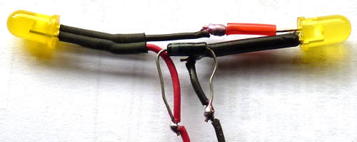
LEDs subsequently insulated and held together with hot melt glue
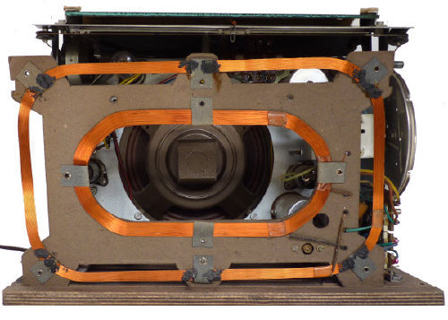
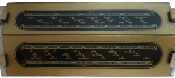
This radio has several less usual features: The on/off switch is coupled to the tone control rather than the more usual volume control. There are two illuminated scales and the pointers move in opposite directions. The components are neatly disposed on a tag board. The chassis can stand unsupported on the workbench for ease of servicing.

