Serial number 6506
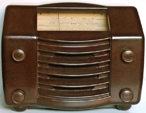
The GEC model BC4940 is designed to operate from AC mains of 200-250 Volts 40-100 Hz. A low voltage version (BC4940L) was also made to suit voltages from115-220 Volts AC and the BC4945 was the universal AC/DC version. All three models cover three wavebands SW 16.5 - 50 m, MW 192 -550 m and LW 1000 -2000m. Valve line up: X61M, KTW61, DH63, KT61 and U50. The 6.5 inch circular loudspeaker is date stamped 16 Nov 1948 and some of the capacitors have a date code 46/48. All three models were first manufactured in October 1948.
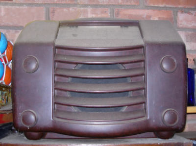
It was given to me by Milford Harrison who remembers it as a child. He grew up with the "the radio" and remembers particularly Hancock's Half Hour on it in the 50s and he tended to look at it when it was on so it was a visual memory too - it was a wonder at that age. In the early 60s (FM!) it was replaced with a Hacker Mayflower 2 (also now in my collection) so the GEC went to an outside shed/workshop where it was used until his dad died some 30 years later. The picture below shows its former home.
In January 1949 GEC were promoting this radio in the following terms:
"Expensive set performance at a popular price. This was the demand at every stage in the manufacture of this BC4940 5-valve superheat. Reception is remarkably good on all wavebands. Quality of reproduction with the high fidelity speaker is superb. Cabinet design in mottled brown plastic (it is actually Bakelite) is outstanding. Price (including purchase tax) £20. 8s.10d"
A copy of the service sheet an schematic diagram can be found here: http://www.radiomanuals.info/
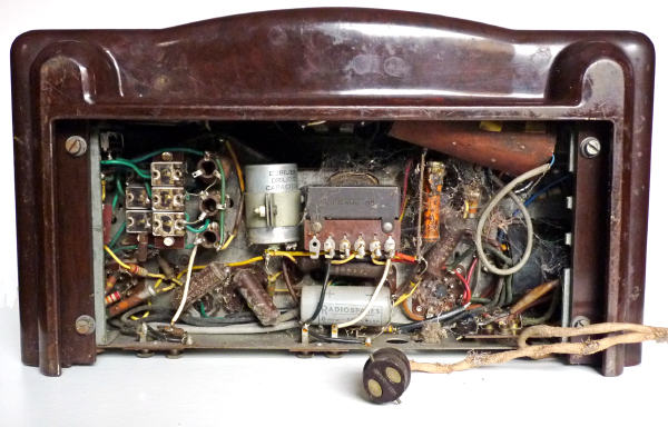
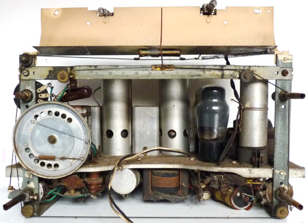
This is a close up view of the underside of the chassis which can be accessed by sliding out a perforated cardboard bottom cover. Apart from the spiders web it can be seen that the electrolytic capacitor is in sore need of replacement and somebody has been there already making capacitor substitutions! The lugs to the 4 / 20 mFd capacitor adjacent to the output transformer had corroded and come completely adrift, an 8 mFd Radiospares capacitor had been wired in place of one half and another (see below) sleeved with a piece of tyre inner tube had been connected across the main 16 mFd smoothing capacitor.

The four knobs are pushed onto steel extension shafts and because of
the rust were very difficult to remove.
It is often difficult to get sufficient grip on recalcitrant knobs to pull them off their shafts. A trick which worked in this case is to pass a loop of strong cord behind the knob wrapping it round your hands and yanking!
I removed the chassis, loudspeaker and glass tuning scale and washed the Bakelite case in warm water. Spots of white paint yielded to brisk rubbing with methylated spirits. The loudspeaker was choked with dust and the cone was damaged on the bottom edge, this was repaired with PVA glue and tissue paper.
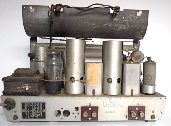
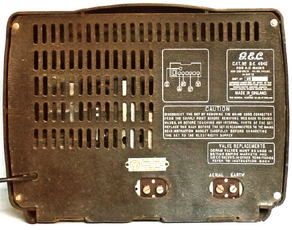
The mains voltage adjustment panel is located behind the metal label on the left. Extension loudspeaker and aerial and earth connections are brought out to screw terminals rather than the more usual banana plug sockets. Were the holes to the left of the loudspeaker terminals intended for a gramophone input?
The volume control is on the top left and the tone control and on/off switch on the bottom right. The wave-change switch operates a coloured (blue, green and red) flag which can be viewed through an opening in the curved cream coloured reflector.
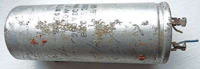
After removing the bulk of the dust, the smoothing capacitors (both original and the replacements) were taken out. The component insulated by the piece of tyre inner tube had been poorly soldered and can only have been making random connection. It was noted that this it was only rated at 200 volts DC (the data sheet indicates a voltage of 297V at this point in the circuit) and that it was a dual unit 24/24 mFd with both sections connected in series opposition. Perhaps it worked!
The casing of the 4/20 mFd capacitor was used to house a 16/16 mFd which I had to hand and the 8 mFd Radiospares capacitor and another were inserted in the tall casing of the 16mFd original component. The casing for the latter was cut open in the area normally covered by the mounting clip. This capacitor is isolated from the chassis by an insulated tape as the negative of the capacitor is returned to chassis via a resistor which provides a bias supply.
After re-soldering the lead to the top cap of the frequency changer and putting the valve shields back in their correct positions, squirting the wave-change switch with switch cleaner, lubricating the pulleys for the tuning mechanism and fitting a new mains lead the set was switched on with a lamp in series to limit the current should there have been a serious fault. It worked on all three wavebands and with full mains voltage applied and a decent aerial there was a lively response even on the short waveband. I tested a couple of the wax capacitors and whilst not perfect decided to leave them alone since it seemed that no other repairs or modifications had been made to the radio in its long life and it was working better than one might expect.

