serial no. A/18 100437
chassis no. 12889
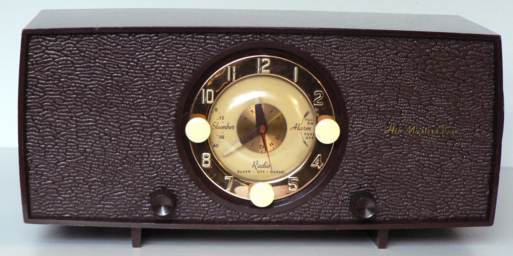
HMV model 1127 Bedside Table Radio with alarm clock and socket to switch on bedside lamp or other appliance. The radio can be preset to automatically switch on the radio or the alarm. Housed in maroon thermoplastic case with medium wave tuning control knob engraved with wavelengths on right hand side. Volume control and wave change switch are either side of the clock on the front panel. The medium waveband is fully tunable but the long wave is set to a single frequency (200kHz). Valve lineup:12AH8 6OBJ6 12AT6 19Q5 35W4. The valve heaters are wired in series and supplied via an auto transformer. The side mounted loudspeaker is of the energised type and the coil forms part of the high tension smoothing circuit. when first produced in 1955 this radio cost � 19 19s plus purchase tax (which I believe at this time was 50%) AC Mains UK 1955
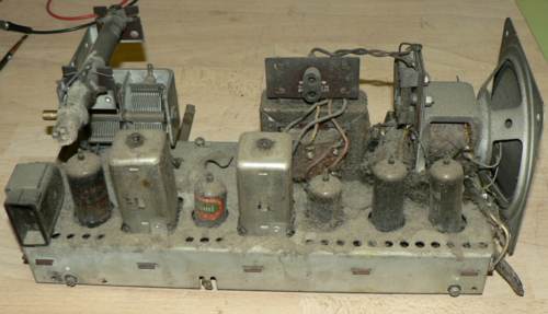
This is what the chassis looked like when I removed it from the case. The mains lead had been cut short but otherwise the set looked intact and unmodified. I purchased one of these radios in 1959 from a work colleague for thirty shillings and it was used for many years until the clock perished. I saw this one recently on eBay and as nobody else seemed interested it became mine.
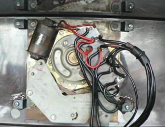
When I removed the clock I found that the lower fixing bosses were broken and that the clock mechanism was almost solid. After washing and polishing the cabinet I used a two part epoxy adhesive and two Bakelite washers to repair the broken bosses. You will see the repairs adjacent to the holes for the control spindles. White spirit was used to clean and free the clock mechanism after which it was lightly oiled.
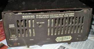
Rear of radio as received. The switched power output socket is on the left.
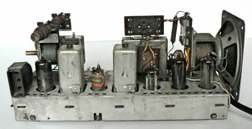
Chassis after cleaning. Note that the valve bases are set below the chassis which makes them difficult to insert.
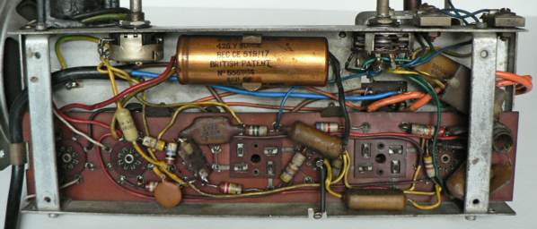
The main electrolytic smoothing capacitor is dated Sep 1955
The construction is unusual, the valves and the IF coils all plug in to an insulated board with recessed wells into which the interconnections,resistors and capacitors are soldered. The board itself is held in place by two spring clips. One of the problems of this method of construction soon became apparent! The resistance between the grid and the HT negative line was less than 3 megohms which indicated that the 10 megohm resistor on the grid was faulty, but no, it was perfectly OK. The culprit was dirt on the upper surface of the circuit board between the adjacent pins on the 12AT6 valve holder. Apart from this the coupling capacitors on the volume control and the grid of the output valve needed replacement.

