Front of instrument with probe
Serial number 1142G020019
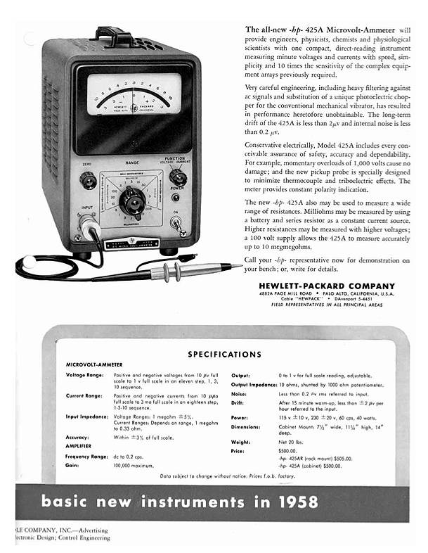
hp- 425A Microvolt-Ammeter
High sensitivity, high stability microvolt meter reading full scale
voltages of 10 microvolt to 1 Volt in 11 ranges. Also reads currents of
10 pico amps to 3 milliamps in 18 step, 1-3-10 sequence. Accuracy + 3%
on all ranges. Drift less than 2 microvolts referred to input
terminals. Input impedance 1 megohm +/-3% on all ranges. Instrument can
also be used as a 100 dB amplifier providing up to 1 Volt output from
signals as small as 10 microvolt. Amplifier
ac rejection is at least3 dB at 0.2 Hz 60 dB at 60 Hz. In addition to
engineering uses, ideal for physics, chemistry applications including
grid or photomultiplier tube currents, ionization levels, thermocouple
potentials and voltaic currents. Also measures voltage in living cells,
nerves, seeds, plants. Includes probe $500.00.[3900 dollars today]
(from HP publicity material 1958)
Made in W. Germany, though all components appear to be of American
manufacture.
Front of instrument with probe
At some time before I received this interesting piece it had been dropped. The socket for the probe was damaged and the set zero potentiometer had been forced backwards into the casing and had come apart. By removing the meter, knobs and mains switch it was possible to remove the front panel and get access to the socket which I filed down to remove the damaged threads and reassemble the potentiometer. The instrument then worked on two of the voltage ranges [3V and 1V]. Sometime later after obtaining a schematic diagram and puzzling over the complicated switch circuitry I discovered that the .0047 capacitor adjacent to the zero set potentiometer had a broken connection. A replacement capacitor has enabled all ranges to function.
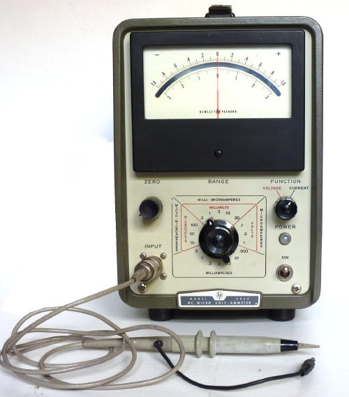
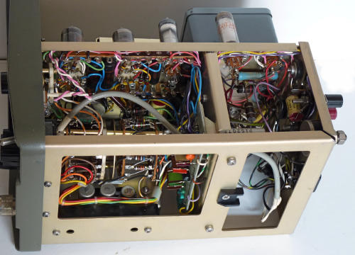
Side view [modulator cover removed]
The amplifier comprises three double triodes 5751, 12AX7 and 12AT7 and the stabilised power supply included 6X4, OA2 and OB2, though the 6X4 had been replaced with two silicon diodes. Perhaps this was done in 1973 when the instrument was repaired and calibrated. The 5751 is a low noise version of the 12AX7 and its heater voltage is rectified.
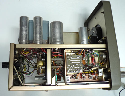
Underside view
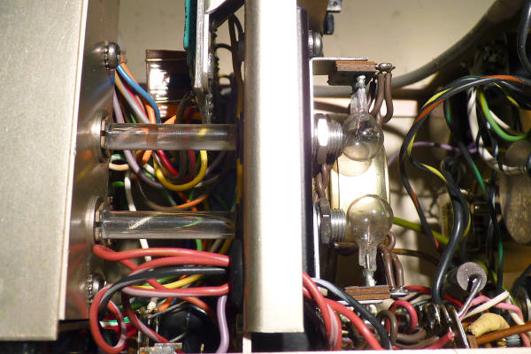
Modulating system
The DC input signal is modulated at 50 Hz by an assembly comprising a synchronous motor turning a shutter, two incandescent lamps and two photo resistors situated at the end of the two light pipes seen above. The chopped signal is amplified and demodulated via two additional lamps and photo resistors, the resultant DC signal is applied to the meter movement and two terminals at the rear of the instrument.