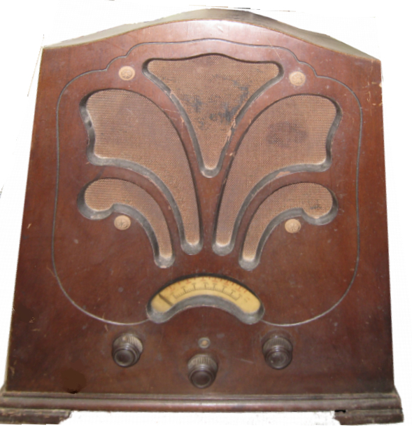
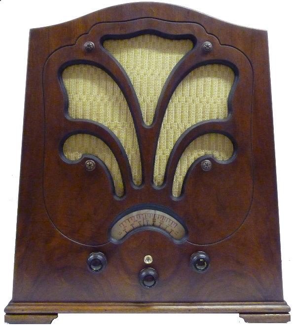
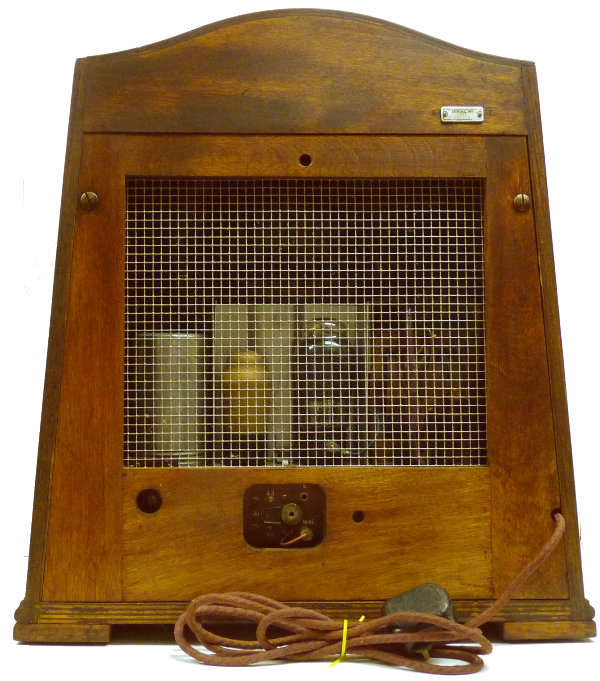
As received and as restored front and back
serial No.253-352200
chassis No. 12100D
As received and as restored front and back
Marconiphone model 253 Four valve Long and medium wave band AC mains operated table top valve radio housed in veneered wood case. Made in UK 1933
This radio was given to me in 2013 by Ian
Rea.
He rescued this one from the loft of his mother's house when she
moved
some years ago. As can be seen from the pictures it was in a poor
condition but seemingly complete and unmodified. A penciled note on
the chassis indicates that it was repaired in May 1945 but I could see
no obvious repairs. Several
problems that would need fixing were immediately obvious when the
chassis was removed from the case: A new rectifier valve would be
needed, the HF amplifier valve would need repair, the loudspeaker cone
would need support, the dial assembly would need re-stringing, the
inter valve transformer and the metal can
housing capacitors had overheated and leaked black pitch over the
chassis. With all the valves removed I energised the set and checked
the mains transformer, all seemed OK and the pilot lights worked. The
loudspeaker produced a click from a 9 volt battery and the field
winding and output transformer checked OK for continuity. A successful
resurrection seemed possible! The other obvious discrepancy was
that the valves were all of Mullard manufacture rather than the Marconi
ones specified (see specification lower down the page)
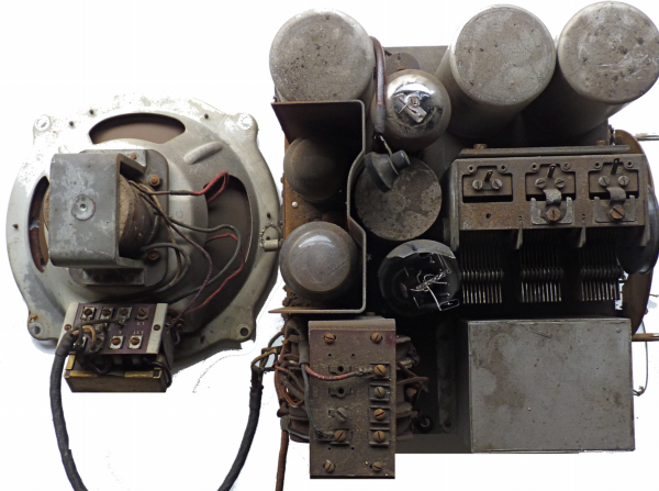
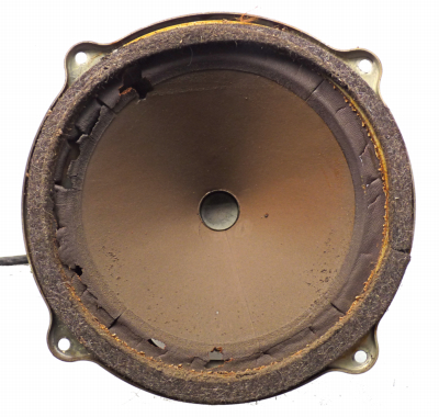
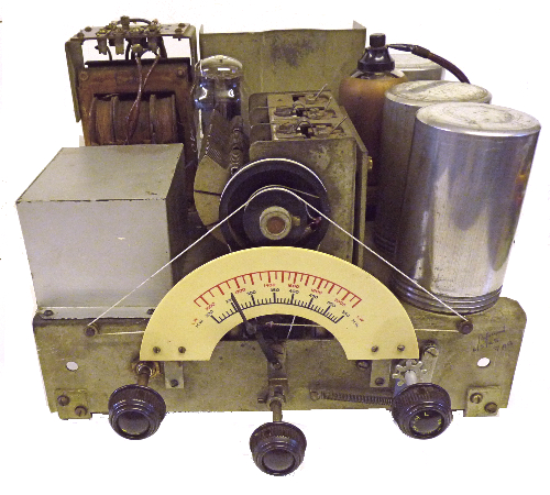
Chassis and speaker as received (note the broken rectifier and
broken valve top cap)
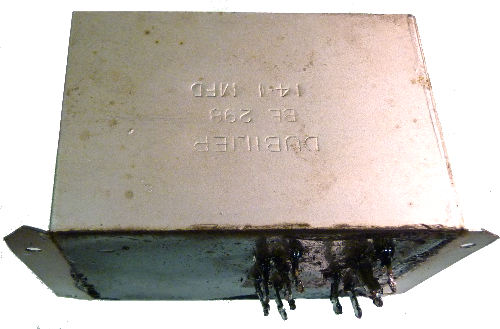
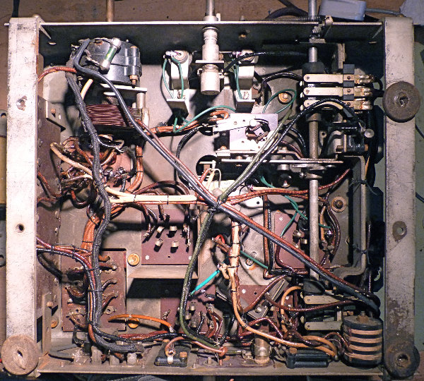
The majority of the paper capacitors are housed in a wax and pitch
filled tin plate box manufactured by Dubilier. The connections can be
seen on this view of the underside of the chassis. The inter valve
transformer together with two associated capacitors are housed in a
pitch filled heavy cylindrical screening can. With some difficulty each
was gently heated and the contents extricated. The transformer was OK
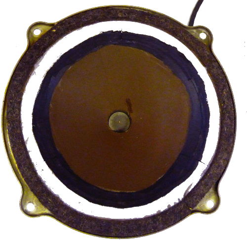
but all the capacitors were discarded and replaced. The loudspeaker
cone moved freely and the rotten flexible peripheral support was
carefully scraped away and replaced with a piece of cotton fabric (from
an old shirt) glued in place with PVA adhesive.
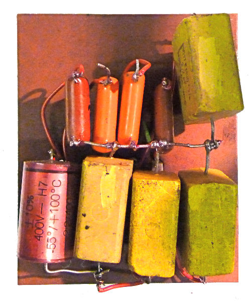
Replacement
capacitors wired ready prior to being held in place with hot melt glue
and fixing in the tin plate container. The loudspeaker repair is not a
thing of beauty but it won't be seen.
As can be imagined getting the capacitor assembly out and back in
place was not the easiest of tasks but went well without mishap. The
transformer had me beaten for quite a while, I had muddled up the
connections and one wire was making contact withe the screening can.
Fortunately the wire on the top of the HF valve was long enough to
solder an extension and re-attach the terminal which I super glued in
place. With a replacement full wave rectifier and when attached to a
fairly substantial aerial the set now works well, though some care is
needed to tune weaker stations juggling between the volume/reaction and
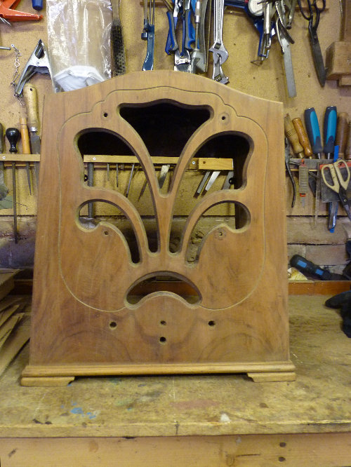
the tuning controls is necessary. The varnish on the veneered wooden
case was in poor condition so I decided to strip it , apply a coat of
stain (American Walnut) and finish with Danish oil. The celluloid
dial window was discarded and replaced with a piece of glass and a new
piece of speaker grille cloth was glued in place. Finally four new felt
feet were fixed to the base.
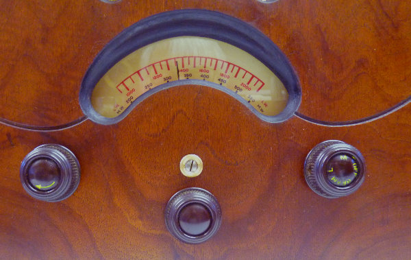
The brass screw
operates in a similar way to the zero adjustment on a voltmeter.
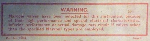
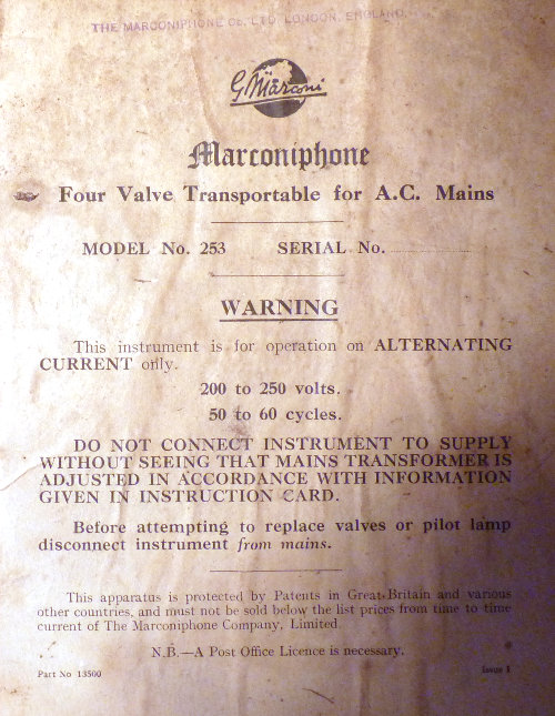
These two labels are
on the inside of the wooden cabinet
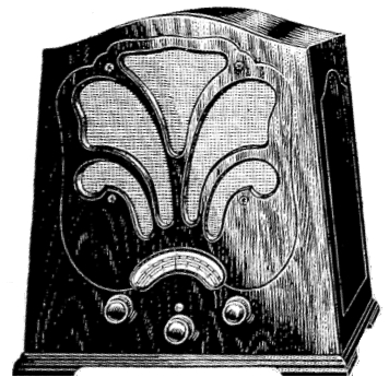
Picture from a 1933 catalogue
Original Specification
VOLTAGE RANGE 200 to 250 volts AC 50 to 60 Hz. This instrument is
designed to work only on the voltages for which it is adjusted. Should
any variation be experienced the supply company should be notified
immediately.
IMPORTANT-This instrument must not be connected to a supply point which
is "fused" for more than 5 amperes (working current).
CURRENT CONSUMPTION. 65 watts (approximately).
SPEECH OUTPUT 1.25 watts (approximately). 8 watts anode dissipation.
WAVELENGTH RANGE 200 to 550 metres (approximately) and 1000 to 2150
metres (approximately).
CIRCUIT DESCRIPTION.
Model 253 is a 3-tuned circuit band pass radio receiver with special
aerial toppings which ensure the utmost degree of selectivity. The
secondary of the band pass arrangement is connected to the grid of the
Screen Grid High Frequency Amplifier-Marconi MS4B. The
sensitivity of this valve is controlled by variable resistance VR1
which is operated by the volume control knob.
Reaction Also coupled to the volume control knob is the variable
condenser VC4 which controls the reaction coils L7 and L8. Choke (CK1)
and condenser (C5) couple the M54B to the tuned grid coils (L5 and L6)
of the
Detector Valve (Power Grid Type)-Marconi MH4.The detector valve
is resistance capacity coupled to high ratio L.F. transformer, which Is
in turn coupled to the
Output Valve (Pentode)-Marconi MPT4.- The transformer T3
(mounted on speaker) receives the output of the MPT 4 and transforms it
for the speech coil of the electromagnetic moving coil speaker.
The high tension supply is derived from the
Rectifier (full Wave Type) Marconi U12

