S/N 98118
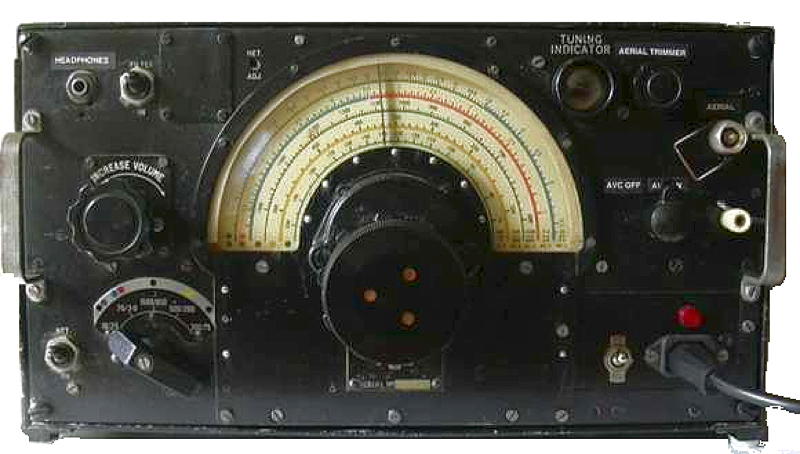
R1155B 5 band communication receiver used in aircraft during and after WWII fitted with internal power supply
The R1155 is a British LF and HF superhet receiver covering from 75kHz to 18.5mHz in 5 bands, with D/F (Direction Finding) and homing functions, they were installed in conjunction with the associated T1154 transmitter in Lancaster bombers and other aeroplanes as well as ground and marine installations. Consequently there were a number of variants:
R1155
Aluminium case
R1155A Aluminium Filters
fitted to prevent interference from MF transmitters
R1155B Aluminium Same as A
but HF chokes added to prevent interference from radar
R1155C Aluminium Same as A
but modified for HF D/F obsolete
R1155D Steel case
R1155E Steel case MF filters
R1155F Steel case HF chokes
R1155L Aluminium Same
as B but frequency range changed to 200-500kHz, 0.6-18.5mHz. for
Coastal Command
R1155M Aluminium MF filters.
For use only at ground schools (due to use of corrosive flux)
R1155N
Steel Same
as L for Marine craft.
I acquired this R1155B five band communication receiver (with direction finding components removed) housed in its proper wooden transit case. The set had been modified to include a 25L6 output stage by wiring the remaining valve heaters in series and providing an HT supply (between HT+ and chassis!) from a HW rectified supply apparently energised from 110 volts AC. V6 had been replaced with a VR55 double diode triode the heater of which had been shunted with two 3 ohm resistors in series.
The interior appeared to be in good condition for its age,
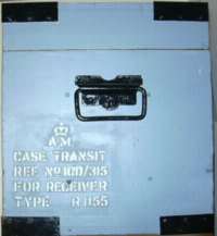
presumably because it had been stored in its transit case for much of
its life. The case however had been painted black some time in the past
and subsequently used as a saw bench! The R115B is electrically
identical to the R1155F as can be seen from the circuit diagram here: http://www.vmarsmanuals.co.uk
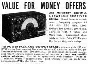
Many thousands of these radios came on to the thriving Government Surplus market in the early 1950's. This typical advertisement from January 1953 shows they were, in today's terms, relatively cheap. However, to put this into perspective it is salutary to remember that the average wage in the UK in 1953 was � 8.30
The case was stripped using "nitromors"
paint stripper and hand
painted using a home made mixture of black, white and blue paint. The
area with the original markings was masked and separately stripped.
case after repainting and making new
steel corner piece
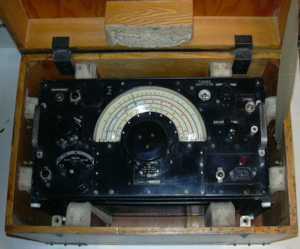
receiver
mounted in box
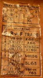
valve identification chart
After disconnecting the connections to the rectifier and the enormous electrolytic, I energised the set with a gradually increasing voltage from an external DC supply to make sure that nothing went bang prior to applying any volts to the heaters. Then throwing caution to the wind energised the heater chain with about 50 volts and was rewarded with the knowledge that there was definite hope, I heard faint signals on all bands.
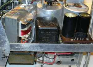
With the help of a circuit from the web, I have removed the the output stage, rectifier valve, wires that started somewhere and ended nowhere, rewired the heaters for 6 volts AC and built and installed a power supply with a more appropriate 230volt HT supply from a transformer fed silicon full wave rectifier. The transformer above the chassis (from an old record player) originally had a 25 volt centre tapped winding which I removed and then rewound to give 6.5 volts and 17 volts, the latter being connected to the transformer (from a grundig dictaphone) below the chassis. The rectifier and electrolytics came from a defunct computer monitor. The Jones plugs have been removed and a mains switch, neon and 3pin power socket mounted on a carefully shaped and painted piece of aluminium has been put in their place. I removed the VR55 and replaced it with the VR101 from the BFO section and found that a 6Q7GT works as a satisfactory replacement for the BFO VR101.
I have been lucky with the rubber insulated wires, the few that crumbled and too difficult to replace have been touched up with two coats of my wife's rejected nail varnish.Several capacitors including C95,C32,C33 and C36 have been replaced (new components inside original aluminium cans). Two wax covered paper capacitors and two out of tolerance resistors have also been replaced.
I downloaded more information from Keith's site http://www.royalsignals.org.uk
I now have it working on all bands but the sensitivity (especially on the lower frequency ranges) seems poor but the standard frequency at 10 MHz was within the pointer's thickness of being spot on, though BBC Radio 4 on 198 kHz was about 194 on the dial.
The excessive noise on the 75-200 kHz band led me to suspect the aerial coil L6 may have shorted turns. I checked through the wiring for the switch FSxr and all seemed OK. The resistance of this winding was 42 ohms though the figure given in the AP2548A is 57 ohms. I was reluctant to take the thing apart and rewind if there might be variants on the design of the coils. (other coil resistances seem to be about 5% low so I assumed these are OK)
Responses to queries on the web elicited offers of spare coils and advice so I spent the best part of a day taking the coil apart and putting it back together. I removed the outer centre tapped DF winding and screen to find that the main winding is in 4 sections wound with Litz wire. It still measured 42 ohms, so I carefully scraped away the covering of the winding adjacent to one of the dividers with a view to determining which section was at fault and I found that the resistance had mysteriously increased! I must have exerted sufficient pressure to move the wires slightly. (Interesting 42X4/3=56?) I applied a little more melted wax and put all back together and it works.
I still found a lot of noise on bands 4 and 5. The IFs seemed to be lined up OK and I have tweaked the trimmers at the HF end of each band and the dust cores at the LF ends. This made a marginal improvement.
The main culprit was a strong local station (in London) transmitting on 558 kHz and once I had reset the rejector filters for minimum output I noticed an improvement, though inserting series and parallel rejector circuits between the aerial connectors and the set seems to have solved the problem. See below:
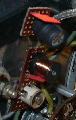
The inductors were salvaged from the same defunct computer monitor mentioned above!

