I have had quite a few enquiries concerning old radios, their age
and value. As these are things that I would like to know as well I
have started assembling another page including the results of my
searches on the internet and old books. I hope you find it
interesting and that you will let me know of any errors and useful
information to add. Note that this page relates mainly to valve (or
tube) radios, if you have a transistor radio it would have been made
after 1954, but much more likely to be after 1960.
A brief summary of some of my radios over the century since public
broadcasting began will give you an idea how world events and
technology can be seen here Wireless
sets
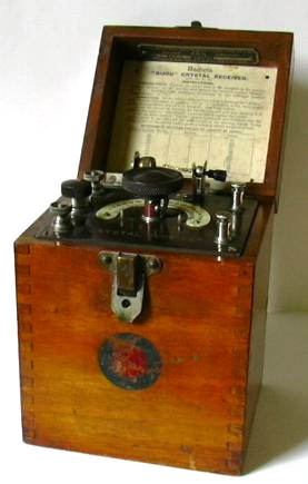
Until about 1927 radios tended to look like pieces of scientific equipment, with the valves sticking out of the top or the front of the set, they often had two or more calibrated dial knobs and were used with headphones or a separate loudspeaker. Until this time valve radios only used triode valves which generally had 4 pin bases.
Between 1922 and 1924 British manufacturers were required to have their sets approved by the GPO and they will have a BBC stamp and registration number (home made sets were exempt). Some British made sets continued using a modified BBC logo without the words "Type Approved by Postmaster General" during the period 1925-7.
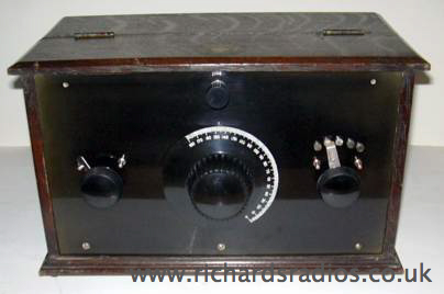
After this the valves tended to be inside a wooden box. Though bear in mind that there was a thriving trade in home made radios throughout the period 1930-1940 made to earlier simple designs.
Around 1932 radios started to incorporate a tuning dial calibrated in wavelengths and a built-in speaker behind a piece of decorative cloth.
Between 1932 and 1936 the Art deco style was popular and about this time Bakelite cabinets started to be introduced. Sets of this period usually have a small, quite simple dials, with no station names.
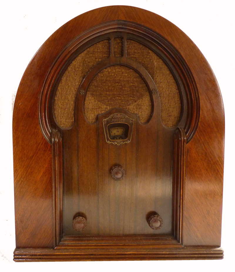
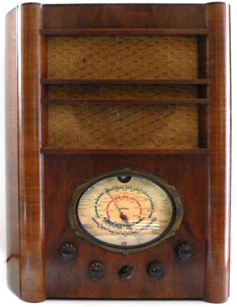
After 1936 many sets had a short wave band and big glass dial with coloured markings showing the station names. American sets contrary to the European tradition seldom had the stations marked on the dial but instead were calibrated in kHz or MHz, a tradition which carried through to the transistor age.
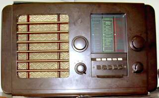
Between 1936 and 1940 radios tended to incorporate more features including additional wave bands, push button or even motorised tuning mechanisms, larger speakers and more powerful outputs.
Sets manufactured between 1940 and 1945 were had very few extra features. British sets made during this period will usually have the Home and Forces wavelengths marked on the dial.
The immediately post war sets look very much like the 1939/40 models though there would have been many changes inside the cabinet as a result of military war time innovation.
The next real milestone was the introduction of domestic FM broadcasting in 1954 and the first FM sets were made in the UK. However for many years cheaper sets did not have FM coverage.
Note that FM sets were available in America during the 1940's covering the range 21-100 MHz.
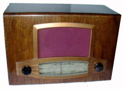
During the late 1950s and early 1960s many sets had piano-key wave change switches and had gold trim and knobs.
Some radios have their dials calibrated in metres (meters) and others in KiloHertz (kHz) Mega Hertz (MHz). One kilo hertz = one thousand cycles per second (kc/s) and one mega hertz = one million cycles per second (Mc/s).
The product of the frequency and the wavelength of a radio signal is equal to the velocity of propagation of wireless waves which is the same as the velocity of light. Numerically: metres X Kilohertz = 300,000 click here for chart
Radios for the British market
The Long Wave National transmitter changed from Daventry (4XX) to Droitwich in 1934. So if it says Droitwich on the dial, it's after 1934.
Dials after 1935 no longer showed North National or Scottish National transmitters. The Regional stations from 1935-39 were: London, 342.1m, Midlands, 296.2m, North, 449.1m, Scotland, 371 m, West on 373.1m and Northern Ireland on 307.1 m. You may find Radio Luxembourg on 1293 m (previously 1190m) and Fecamp/Radio Normandie on 226.1m (223 m previously) on dials from this period
During WW2 1939-45 the BBC's domestic services were known as the Home and Forces programmes. After the war the Regional system was re-introduced, and dials will show London Home Service, Midlands Home Service, etc., the wavelengths being: London, 342.1 m, Midlands, 296.2 m, North, 449.1 m, Northern Ireland 285.7 m, Scottish, 391.1 m, Welsh, 373.1 m and West, 307.1m and 216.8 m. The National programme was replaced by the Light programme, as previously on 1500 m plus a number of relays on 261.1 m. Some sets retained National on their dials for some time after the war. These wavelengths remain unchanged until 1950. Radio Normandie, closed down in early 1940, but Luxembourg came back on 1293 m. Sets made after 1947 will include the Third programme on 514.6 m and 203.5 m.
In March 1950 the Copenhagen Plan came into being. This meant more changes and dials after this date will show London, 330 m, Midlands, 276 m, North, 434 m, Northern Ireland, 261m, Scottish, 371 m, Welsh, 341m and West 206m. The Light programme stayed put on 1500 m, but the medium wave transmitters changed to 247 m. and the Third went to 464 m and 194 m. Radio Luxembourg 208 m started at this time. The next major change was in May 1955, when the first VHF transmitter (Wrotham) came into full service. The earliest UK FM radios date from this time. Radio Caroline (199m), the first of the pirate radio station came on air in 1964.
Triangles
You may observe that some dials for sets marketed in USA are marked with two triangles at 640 and 1240 kHz, this means that the set was made between 1953 and 1963.
Why?
President Truman established the CONELRAD [CONtrol of
ELectronic RADiation] system in 1951. to provide emergency
alert to the public. Under this first national alerting system in the
event of a Soviet attack on the United States, all commercial radio
stations would cease normal operation, in order to prevent Soviet
bombers from homing in on their targets by using specific radio
commercial radio stations as navigation beacons. Instead, selected
CONELRAD stations would broadcast on either 604kHz or 1240kHz to
inform the public about emergency measures. As part of the system it
was obligatory for all radios sold after 1953 to have the
CONELRAD frequencies 640/1240 kHz marked with small triangles on the
dial. The triangles were referred to as CD marks, for Civil Defense.
The marks on the radio dial were to make finding the frequencies
easy. By the early 1960's the development of Soviet missiles had made
the CONELRAD system obsolete and this requirement was dropped, when
the CONELRAD system was replaced by the Emergency Broadcast System in
1963.
UK FM radio scale markings
VHF FM broadcasting started in 1955,
initially only for BBC stations gradually the band was extended to
include commercial and local radio stations.
1955 88.1 - 97.6
1972 88.1 - 102.4
1983 88.1 - 104.5
1983 88.1 - 108
The very early valve sets use triode bright-emitter valves. These will date the set roughly as 1927 or before. Triode valves of this period had 4 pins. A valve bearing the letters BVA will have been made after 1924
Some time later manufacturers provided the filament with a more efficient coating on which enabled it to be run at a lower dull red temperature. Most valves of this period were evacuated through the top of the bulb leaving a spike where the glass envelope was sealed. Sets using only dull-emitter triodes will most likely date from 1930 or just before. The screen grid or tetrode valve was introduced in 1927, the additional connection being made by adding an insulated terminal on top of the glass envelope (the push on connection came later). Mazda started making valves in 1928 and Philips/Mullard introduced the PM range of valves in 1925.
The next development was the pentode valve which appeared in 1928. This saw the introduction of valves with 5 pins on the base.
Around this time valve makers started making valves for mains-powered sets, which by 1932 were becoming a reality. A specially coated shield or cathode surrounding the filament was introduced. This meant that AC could be used to heat the valves without causing hum problems. One of the major changes was the need for more pins on the valve base, and for the first time, valves with seven pins were made. American valves of this period had similar glass envelopes but the bases are readily identified by having two thicker pins, the bases of which came in 4, 5, 6 and 7 pin varieties.
Metal tubes were introduced by RCA for the American market towards the end of 1935
About 1936, European valve makers introduced the side-contact base. These valves often manufactured by Philips or Mullard in the UK never proved very popular and were soon superseded.
In 1937 the American Octal base valves first appeared in UK manufactured radios. The octal base had eight pins surrounding a central spigot. British valve makers introduced Octals as well. Mazda introduced their own variation in 1938, with a similar base which did not fit in the American Octal socket, the American base prevailed and is now generally referred to as International Octal. Radios manufactured between 1937 until well after WW2 predominantly incorporated valves with octal bases. The move towards smaller radios which started in America well before the war resulted in the smaller GT shape with straight sides and reduced height, some octal based valves are encased in metal.
Wartime advances in the manufacture of valves enabled valves to be made with the pins set directly into the glass. One of the first of the smaller bases was the B7G, which was first imported from America where they were first manufactured in 1942. These miniature valves were very much smaller than the octal GT valves.
A later addition was the B8A base, which was introduced in 1947 with a metal band around the bottom. Some manufacturers made a variant using the same pin spacing but incorporating a central spigot. These valves were used in sets from about 1949, until 1954. In 1953 the base was revised and made entirely of glass.
In 1951, the Noval (9 pin) base was introduced, though some valves with this new base were made as early as 1949 (the Brimar catalogue of this year lists 5 valves). There was a considerable overlap and it is not until about 1954 that sets using only Noval valves were made. By 1956 the 9 pin glass base valve was used almost universally.
An approximate guide showing changes
in physical construction (read in conjunction with the
above)
|
Date |
Envelope shape |
External metallising |
Gettered area of envelope |
Electrode cross section |
Electrode orientation |
Base material |
Wires from electrodes to base |
Number of pins & base |
Date |
|
1920 and earlier |
various shapes with pinch on top |
none |
none |
circular |
not easily classified |
metal sides |
soldered around envelope end of split pins |
4 only |
1920 |
|
1925 |
nearly all |
rectangular |
transverse |
Bakelite some metal sides |
soldered inside hollow pins at free end |
1925 |
|||
|
rounded top pinch in base |
|||||||||
|
1930 |
silver or gilt on HF valves |
small area near base |
many shapes |
axial |
4&5 only |
1930 |
|||
|
shoulder shaped |
6US 7GB |
||||||||
|
1935 |
1935 |
||||||||
|
side contact octal
|
|||||||||
|
1940 |
some red |
1940 |
|||||||
|
1945 |
tubular (GT) |
1945 |
|||||||
|
none |
B8A |
||||||||
|
1950 |
miniature pinch on top |
small area above electrode structure |
glass pins set in base of glass envelope |
inside envelope |
B7G noval 9
|
1950 |
|||
|
1955 |
1955 |
||||||||
|
1960 |
1960 |
||||||||
|
1965 |
1965 |
Most valve radios made before 1930 were of the Tuned Radio Frequency
type and incorporated one, two or three valves (or maybe four if
operated from the mains). By 1935 most sets on the market operated on
the more complex but superior superhetrodyne principle (some American
imports in the late 1920's were superhets)
Until 1955 all radios in
the UK were made to receive amplitude modulated signals. Radios would
generally be capable of receiving signals on the medium waveband and
often on the long and shortwave bands as well. In the mid to late
1950's sets designed primarily to receive the high quality frequency
modulated signals became available, but as coverage was initially
patchy most were still also capable of receiving the medium an long
wave band stations. Early sets from 1955 covered 88-101MHz. In 1972 with the advent of local radio
the range was extended to 105MHz and later, ultimately to cover
the whole of the UK Band II, 88-108MHz. Digital Radio in the UK was
rolled out in 1995.
Many electrolytic capacitors have date codes printed on them (it
may be necessary to slacken the chassis clip to see them) this may be
in the form 4/49 or something similar. Beware that these items may
well have been replaced in the past. Have a look at the loudspeaker
these are often date coded. Sometimes the serial number of the set
can give a clue.
HUNTS and ERIE Date Codes:
The code is read as Year-Month (from 1960). Basic date code translator
is: WHITSUNDAY=1234567890
W = 1
H = 2
I = 3
T = 4
S = 5
U = 6
N = 7
D = 8
A = 9
Y = 0
Basic Example: N YS date code is: 1967-05 --> 1967 May
TCC and RS Capacitors.
A thru Z used except 'O'
YEARS
'Q' = 1959
'R' = 1960
'S' = 1961
'T' = 1962
'U' = 1963
'V' = 1964
'W' = 1965
'X' = 1966
'Y' = 1967
'Z' = 1968
MONTHS
'A' Jan
'B' Feb
'C' March
'D' April
'E' May
'F' June
'G' July
'H' August
'J' September
'K' October
'L' November
'M' December
Typical Date code: TCB/YC --> TCC Capacitor (1967 March)
Typical Date code: PWJ --> RS Capacitor (1965 September)
Typical Date code: ZM P --> RS Capacitor (1968 December)
DALY Capacitors (1971 thru 1979)
YEARS
'Q' = 1971
'R' = 1972
'S' = 1973
'T' = 1974
'U' = 1975
'V' = 1976
'W' = 1977
'X' = 1978
'Y' = 1979
MONTHS
'A' Jan
'B' Feb
'C' March
'D' April
'E' May
'F' June
'G' July
'H' August
'J' September
'K' October
'L' November
'M' December
Typical Date code:
QJ = 1971 September
Conversion of Japanese Imperial years to Western years:
If made before 1989 add 1925 so 30 would
be 1955
If made before 2000 add 1988 so 6 would be 1994
After 2000 previous system abandoned
Conversion of Taiwanese Republic years to Western years:
Formally, years in Taiwan are counted from the founding
of the republic in 1912. Thus, 2007 corresponds to the 96th year of the
republic. Informally, the Gregorian calendar is also used. To avoid
confusion, the Gregorian calendar date year is always written in full.
Also, the term gongyuan (公元, "common era") is used for Gregorian dates
and minguo, (民國,"republic") for the Republic date.
UK
Government date codes were used
on militaryequipment and components
year month
A.1945..A.January
B.1946..B.February
C.1947..C.March
D.1948..D.April
E.1949..E.May
F.1950..F.June
G.1951..G.July
H.1952..H.August
J.1953..J.September
K.1954..K.October
L.1955..L.November
M.1956..M.December
N.1957
P.1958
Q.1959
R.1960
So for example DL would be November 1948
Some radios have patent numbers printed on them. Below are lists of the first patent numbers issued in the given years. The radio cannot be older than the date of the latest patent.
Year U.S. GB.
1920 1,326,899 136,852
1925 1,521,590 226,571
1930 1,742,181 323,171
1935 1,985,878 421,246
1940 2,185,170 512,178
1945 2,366,154 566,191
1950 2,492,944 633,754
1955 2,698,434 724,991
1960 2,919,443 829,181
1965 3,163,865 982,551
1970 3,487,470 1,180,651
1975 3,858,241 1,384,031
Early valve radios were battery operated and were designed to work with headphones. The next improvement in the early 1920's was to use a similar transducer coupled to a horn to allow several people to listen together. Within a year or so the paper cone, moving iron speaker was fairly commonplace, you will find a couple on my website. The moving-coil loudspeaker used almost universally today, although invented much earlier, started being introduced in about 1926. It gave much better sound quality than the horn or moving-iron loudspeakers used previously but initially they had rather low sensitivity due to the difficulty of mass-producing really good, light, magnets at low cost. To overcome this problem early mains operated radios (1930's) were equipped with moving-coil speakers which had electro-magnets and the windings were placed in series with the HT supply.
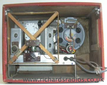
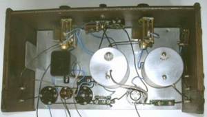
Prior to about 1953 radios generally had provision for the connection of a wire aerial (antenna) and an earth (ground) connections, or if they were intended to be portable or self contained would have a frame aerial like this radio made in 1946
The use of frame aerials gradually faded away with the advent of
transistor radios see one of the first
transistor radios. to be replaced by ferrite aerials the
main advantage of which is their small size.
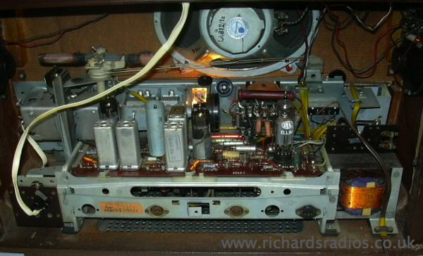
A ferrite-rod aerial is a receiving aerial consisting of a small coil mounted on a short rod of magnetic ferrite. The coil is, in effect, a small frame aerial, and the function of the ferrite rod is to concentrate the magnetic flux from a large area surrounding the aerial. Like all frame aerials the ferrite-rod aerial has pronounced directional properties. In table top sets such as this one made in 1961 the ferrite aerial can be rotated by strings and pulleys to obtain the best signal. This radio is also equipped with an internal aerial comprising two pieces of conducting foil glued to the inside of the cabinet for the VHF band.
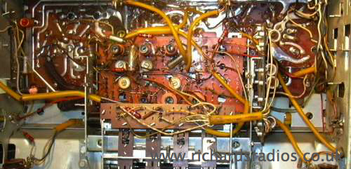
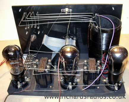
The earliest radios usually employed bare tinned copper wire to connect up the components like this one which is from about 1928:
From this period onwards insulated often flexible conductors were generally employed as this radio from 1929/30 shows:
The insulating material at this time would be rubber or varnish impregnated sleeving. Plastic insulated wiring started to be used during the 1940's as a replacement for rubber which was in short supply. By 1958/9 many valve radios were being manufactured with very little wiring, the connections between the components being achieved with a printed circuit although printed circuit construction was used in the very earliest transistor radios from 1954 onwards: