Before applying mains voltage to a newly acquired valve radio I suggest that you remove the back and look inside:
Blow off the dust and make a note of the valve numbers and their positions, try and obtain a schematic diagram. The valves may be replacements and the numbers may not correspond with those originally fitted.
Are all the valves in the right places? (This is really worthwhile unless you know that the set has been working recently, I have come across sets that have had the valves put back into the incorrect sockets!)
Check the condition of the mains lead, if it's rubber insulated or plastic single insulated you should replace it. Look at the condition of the wiring to the speaker and dial lamps, if it's rubber covered replace this as well.
Check on/off switch is wired in the live side of AC/DC sets. These sets have potentially live chassis so make sure that the neutral is connected to the chassis.
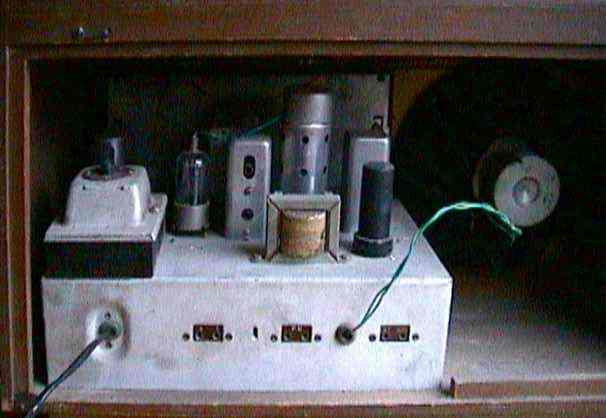
Look under the chassis. are there signs of things that are missing, melted or exploded?
Check voltage tappings on the mains transformer or dropper resistor are in the correct place.
The dreaded line cord On some American radios imported in the 1940's the valve heaters were wired in series and this added up to perhaps 100 volts worth. The dropper for the rest was a series resistance wire wound on what might be an asbestos core run down the length of the mains cable. Coiling the mains cable can be a significant fire hazard. Shortening the mains cable will give the valves a little boost but perhaps not for long! In AC/DC sets for the EUropean market the same effect was achieved with a high wattage chassis mounted resistor. In some smaller radios you may well find an asbestos insulating pad to prevent the casing overheating- take care! Now if you are satisfied that all is apparently well, remember that your radio may have been asleep for many years and the sudden application of full mains voltage may give it a heart attack. You now have two options:
1. Connect a 100 Watt 240 Volt light bulb ( a modern CFL or LED light bulb is not suitable) in series with the live connection and switch on, the lamp should glow red and the set should slowly come to life. If all is well you may proceed to step 4. If it glows brightly switch off, something is seriously wrong!. Proceed to step 2. For further information on the use of the light bulb and much other useful advice see www.vintage-radio.com
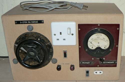
Some people use a "Variac" or variable transformer to gradually
bring up the voltage. I have always used the lamp method described
above but I purchased a large 8 Amp Variac and have housed it in a MDF
box complete with a moving iron meter and socket outlet. This has the
advantage that one can operate equipment designed for 110 volts (the
110 volt socket is below the meter). I have also included an isolated
variable DC supply, the switched output terminals of which are below
the 13 Amp socket.
When I bought this variac I was told that it came from one of the
Cambridge University laboratories. The meter and switch panel were made
by my father at least 50 years ago to monitor the input and output
voltages of an Air Ministry oil filled 3.5 amp variable transformer
which for a 230 volt input would only provide an output of 200-250
volts.
2. Remove the rectifier valve and connect a 250 Volt DC supply to the cathode pin in the valve-holder and monitor the current drawn by the set. If all is well the current will fall away to a few milli-amps as the smoothing capacitors gradually reform. The final current should be less than 10 mA. More than this generally indicates faulty capacitors, by disconnecting capacitors one by one starting with the main electrolytic and then the ones which have dripped wax you should be able to find the culprits.
In AC/DC sets the capacitor that is connected across the incoming mains often causes trouble, it is a good idea to replace it with a modern AC rated equivalent.
3. Replace the faulty capacitors and the rectifier valve and go back to step 1. Hopefully the lamp will glow dimly and you will see all the valve heaters glowing and the dial lamp working, and after a while music in your ears!
4. You may now safely plug the set directly into the mains.
Remember mains powered valve radios can give you a lethal electric shock. Do not touch wiring or chassis whilst the set is energised. Remember that the main smoothing capacitors can hold their charge for a considerable time after the set is switched off.
Remember that you are preserving history. There are different views on restoration, I have the view "if it ain't broke don't fix it." My aim is not to make money from this hobby. I get enjoyment from "bringing back the dead" and making the sets reasonably presentable for their age.
Others strip their radios down to the chassis and clean, plate and completely rewire and then make the cabinet look like new. In some instances depending on the radio the amount of modifications made and how it is done this will reduce its value. For example using the wrong type of finish or stain will affect its value. Electronic restoration too is important, you may find that repairs have been done in the past and that valves with different bases have been fitted and sometimes the old metal filter capacitors have been removed and replaced.
When possible I leave the outsides of any faulty original capacitors and use them to hide modern replacements which are invariably smaller. I know this this extra work but I feel this is a more faithful way of restoration.
Some radios are just full of dust, some with rust and dust and others with dust, rust and greasy grime.
I tend to use a tooth brush, a small artists paint brush with stiff bristles, a pointed wooden skewer and fine grade wire wool (but beware of stray strands getting left behind) Emery paper or emery board nail files for getting into corners.
These are used first dry and then with one or more of the following as required:
water, water and detergent, WD40 (thin spray lubricant) and a powder based metal polish mixed into a paste.
The chassis still looks rusty, but smooth? If plated finish off with silver coloured paste used for renovating picture frames applied with finger, brush or whatever. In UK this is called Goldfinger and manufactured by Rowney. I used this for the first time on this set.
Repairing Bakelite cracks is one of the most difficult tasks in radio restoration. Anyone can glue a crack together using 'Devcon' plastic weld. But to repair a crack so that no marks are left behind is another matter. Please be aware that Bakelite may contain asbestos and take precautions against inhaling any dust.. A Dremel tool is used to make such a repair. First you would cut a groove along the crack and save the dust. Also grind some more plastic dust from somewhere inside the cabinet. Mix with clear epoxy cement and fill the groove over the crack. Grind or sand the cement down. Then polish with rouge to get an even polished surface. It takes a lot of practice to get the expertise needed to make such repairs a success.
The speaker cloth is often badly discoloured. Having learnt the hard way I soak the cloth for some hours in a biological detergent and very gently agitate it prior to drying flat on absorbent kitchen paper. It is then ironed between two layers of cloth.
The radio works fine, but has a hum ONLY when tuned to a station. Try connecting a capacitor between the AC line and radio chassis. A 0.01 mfd. capacitor with an AC voltage ratingsuch as those type X or Y rated for a similar use in a mains filter. For a battery set operating from an AC power supply add the capacitor between AC line of your power supply and radio chassis. Adding the cap between AC line and B- of your supply should also work.Lack of this capacitor is a common problem causing hum when tuned to a station.
Unplug your radio before working on it with a soldering iron, if you
don't you may trip the residual current circuit beraker to your supply.
