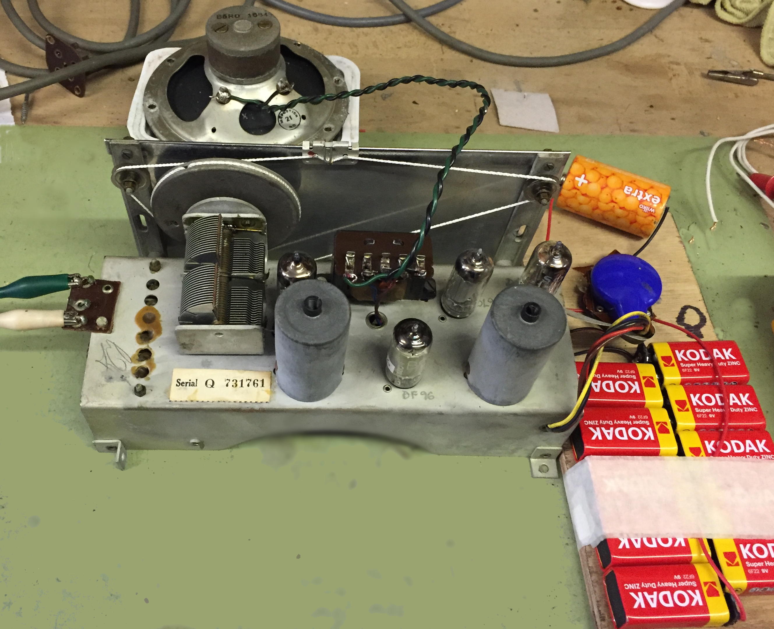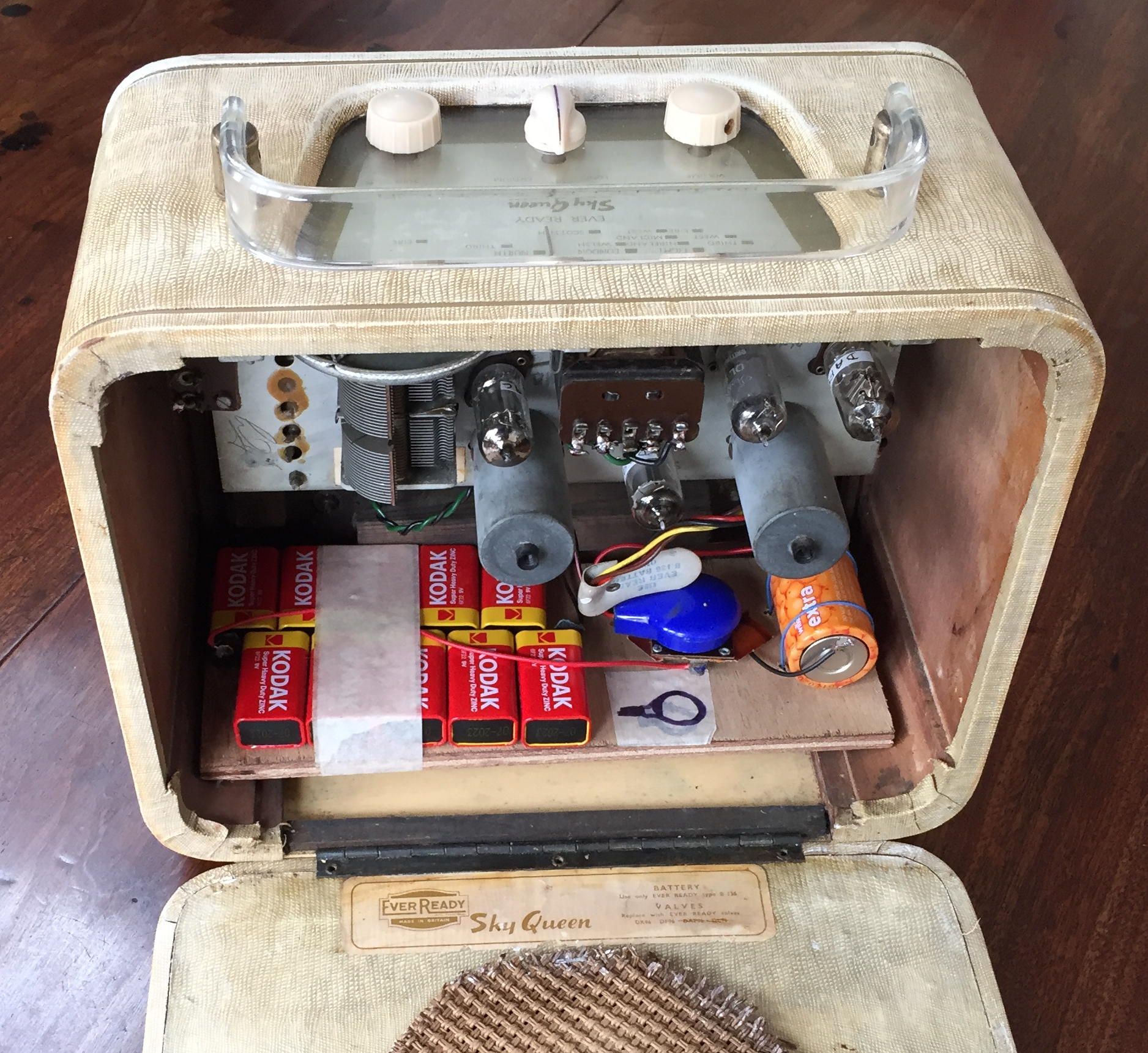
The radio was in poor condition when received and was completely silent when energised from a temporary battery supply made up from ten PP3 9 Volt batteries an a single 1.5 Volt cell. I soon discovered that the filaments of all four valves were open circuit and that the output transformer primary was also open circuit. So spare parts were needed before anything further could be achieved so purchasing a donor radio seemed to be the best option as although replacement valves are fairly readily available a suitable output transformer would not be.
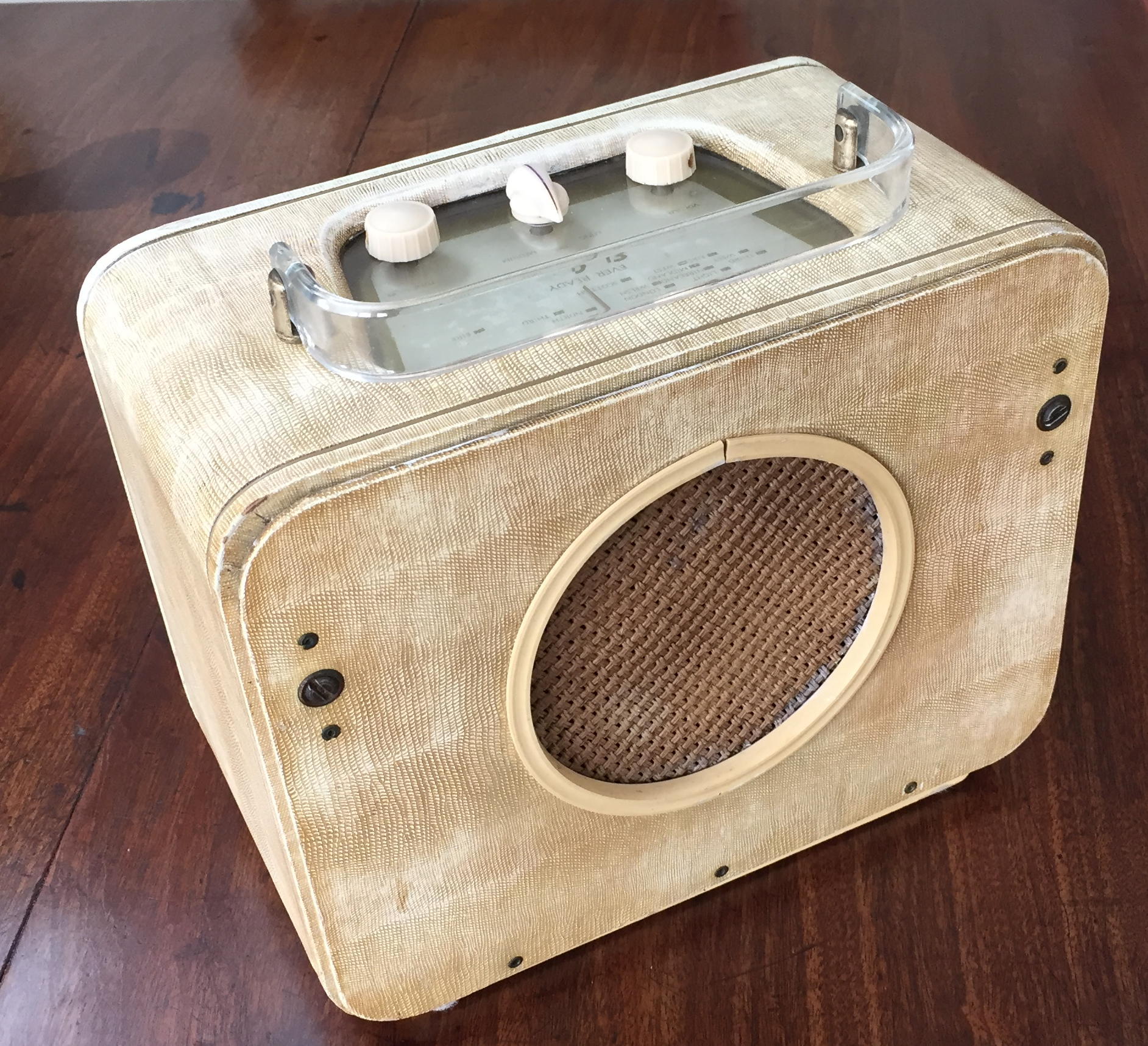
I purchased this woodwormy Sky
King which can be seen to have a very similar chassis and
discarded the case and salvaged the valves and transformer which
brought the Sky Queen to barely audible life. I anticipated that many
of the capacitors would need replacing but did not expect that the out
put valve would be such a poor performer. Fortunately with this
replaced the output dramatically improved.
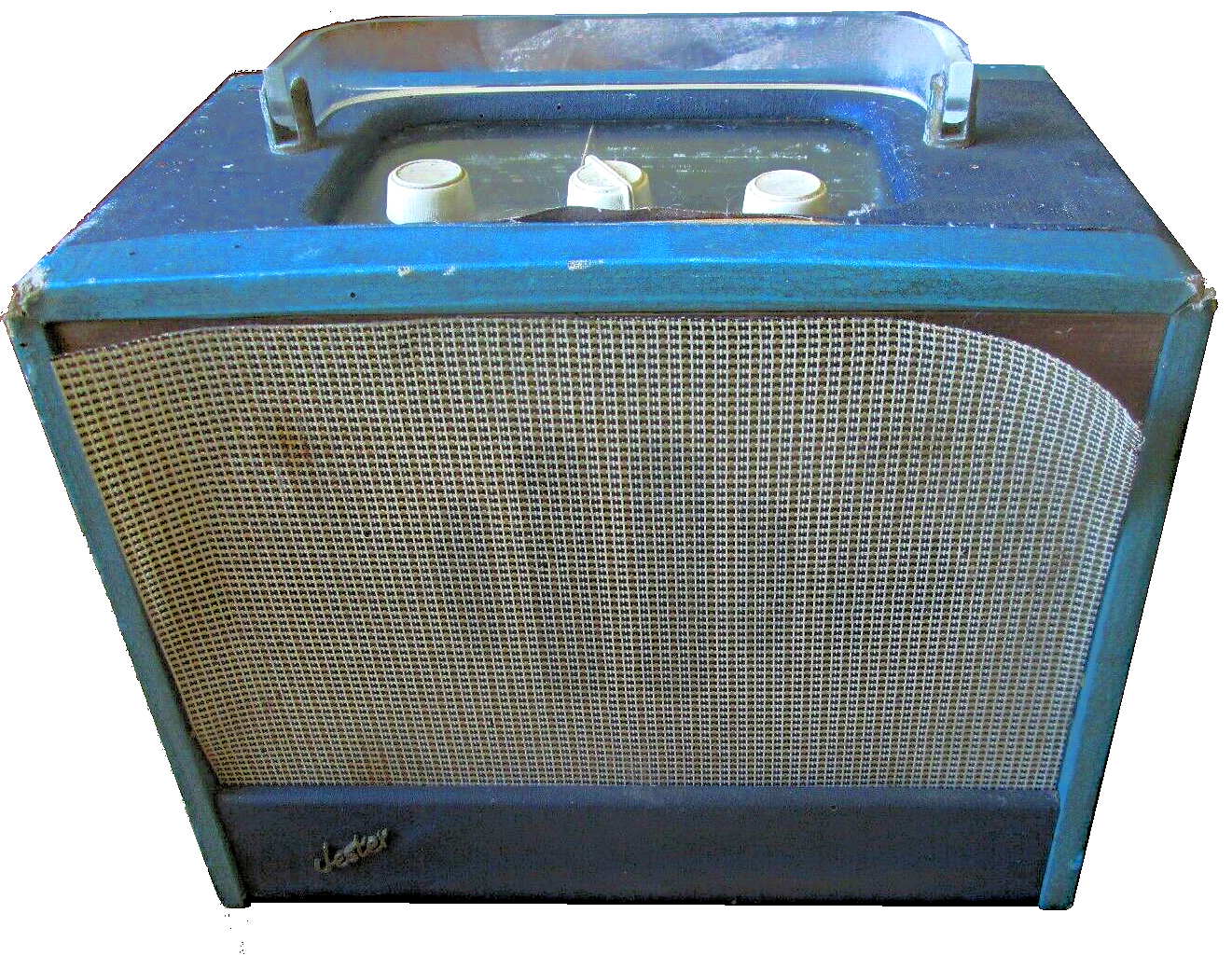
Sky
King Radio in poor condition
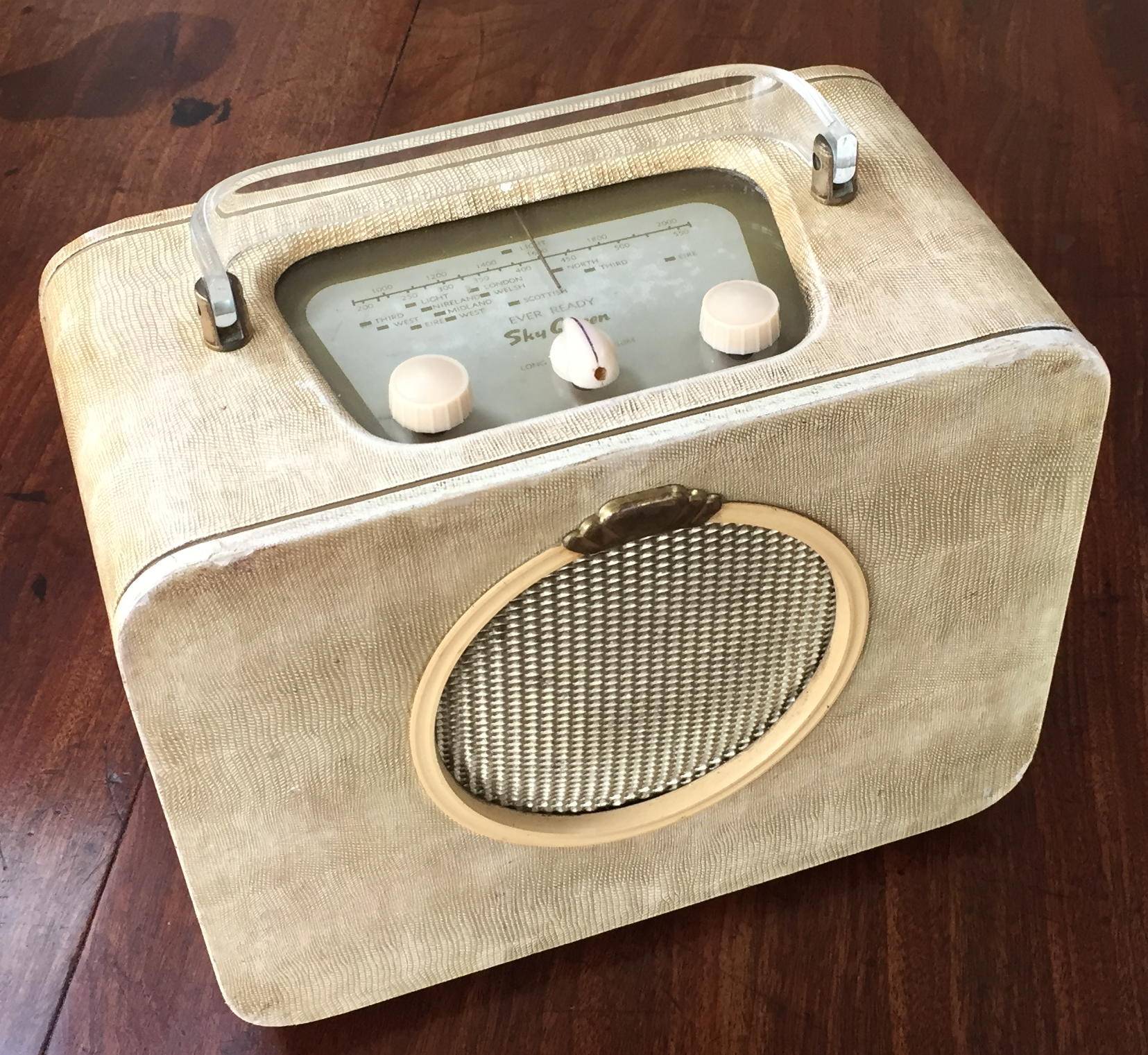
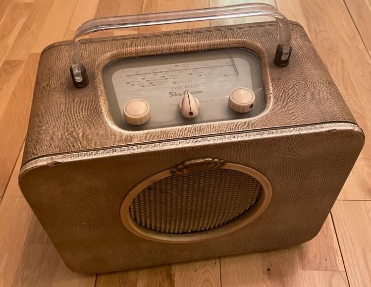
This is one of a series of Ever Ready
battery radios including the Sky King and Sky Prince which employ
almost identical chassis and circuitry.They were manufactured for
several years between 1953 and 1957 and were designed for dry
battery operation using a 90/1.5 Volt Ever Ready Batterymax B136 brick
sized battery. They consist of a conventional Long/Medium wave 4 valve
super heterodyne circuit using a DK96 frequency changer, a DF96 I.F.
amplifier, a DAF96 second detector and A.F. amplifier, and a DL96
output pentode.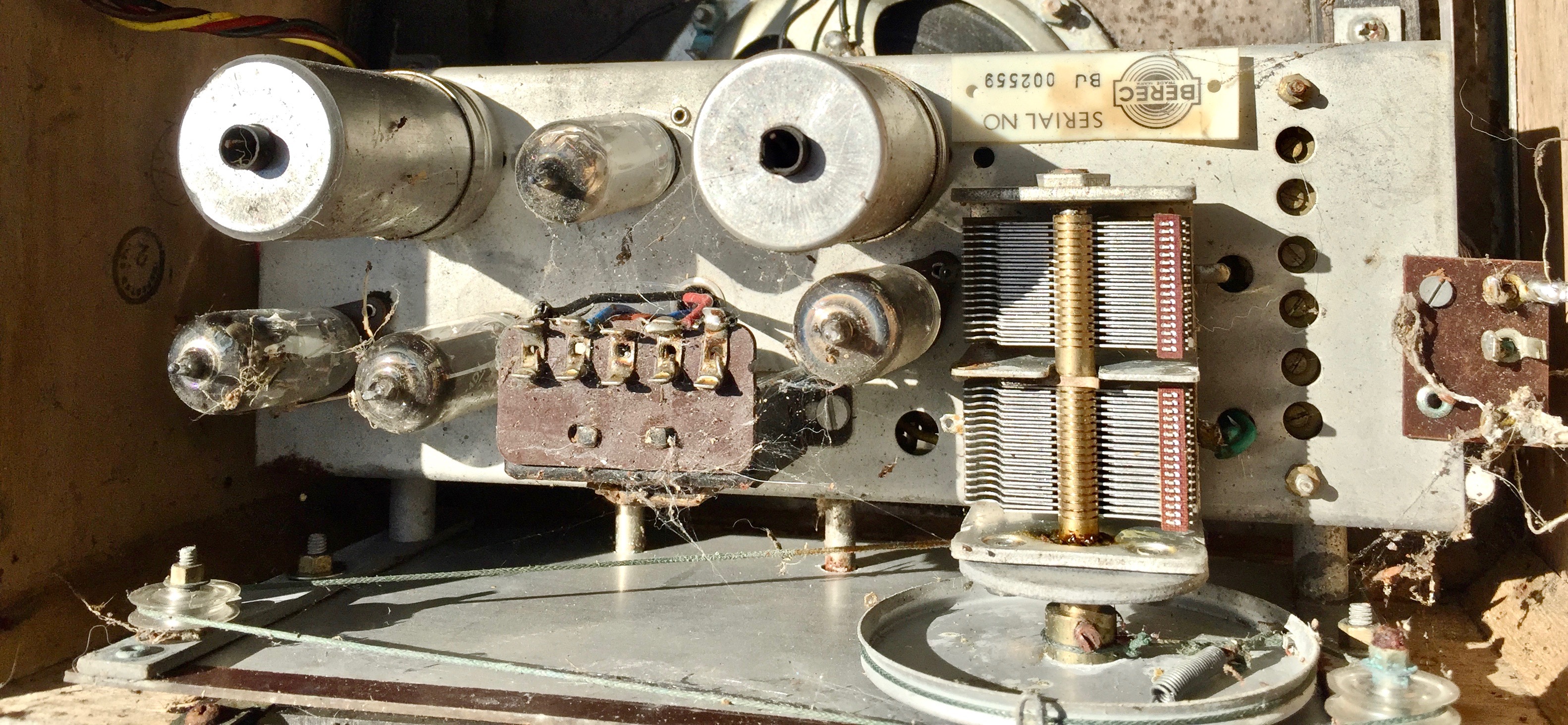
Circuit description
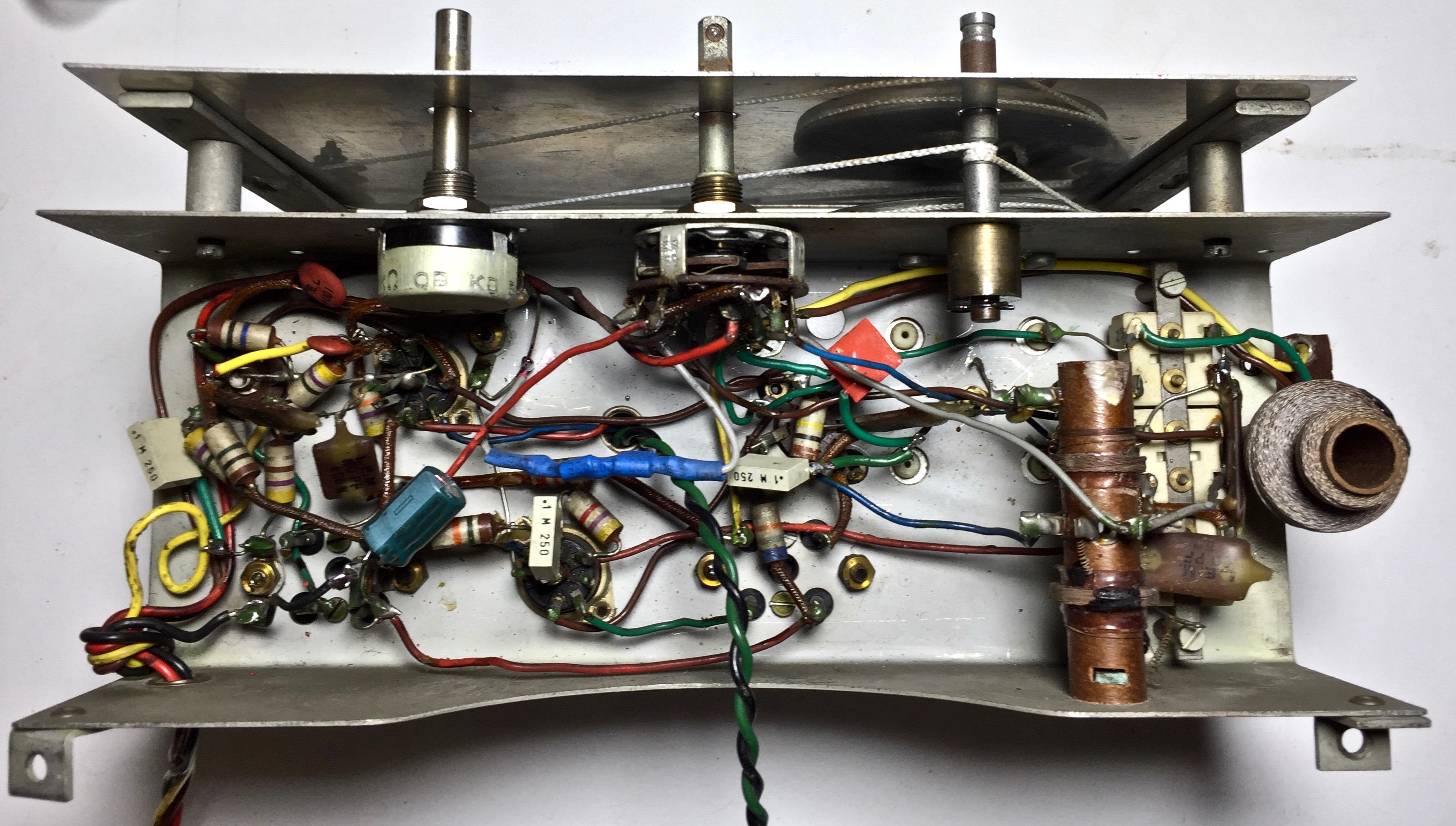
The loop aerial is wound on four pillars mounted on the baffle, and being tuned by C2 forms a high “Q’’ R.F. circuit which is coupled directly to the signal grid of the DK96. The local oscillator consists of a conventional series fed grid tuned type of circuit coupled between g1 and g2. The two signals combine to form an intermediate frequency of 470 Kc/s which is passed via the |.F. amplifier (DF96) to the diode second detector forming part of V3. The resulting A.F. signal is fed via the volume control through the pentode section of V3 (DAF96) to the grid of the DL96, and is then amplified by the DL96 and fed to the loudspeaker. The automatic gain control voltage is fed back from the diode load to the grids of the frequency changer and I.F. amplifier valves.
Controls. Volume control (left). Wave-change and on/off switch. Tuning control (right).