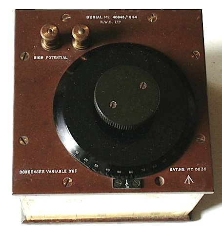
HWS Ltd. Type XBF Cat No WY0835 s/n 40846/1944 Sullivan standard variable Capacitor, housed in polished wood box with calibrated knob 0-180, Calibration table on side of box UK 1944 (ex WD)
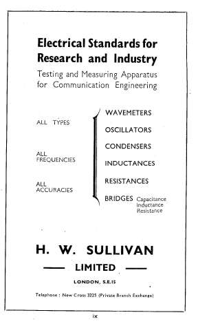
These variable condensers were made as laboratory standards of comparison. Similar condensers by Sullivan and Muirhead are described in the "Radio Laboratory Handbook" 2nd Ed 1943 by MG Scroggie published for Wireless World by Iliffe & Sons. I don't know what happened to Sullivan but they made equipment for the Admiralty prior to WW1 and were well known in the field of precision measuring instruments and made equipment for the National Physical Laboratory. Advert from above book is shown below.
My unit is 650 uuF max and has an essentially linear relationship between the scale markings and capacity. I believe each unit would have a unique calibration chart which enables the capacity between calibration points to be calculated. The third column indicates the capacitance CHANGE (i.e.total MINUS the 50pF "leakage") - i.e. the same as the 2nd column minus 50pF. As you will see the first column of figures is typed and the other two are standard for this type of condenser. My chart is shown here.
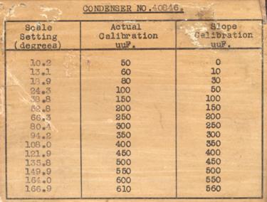
You will note that my unit has a constant stray capacitance of 50uuF i.e. below 10 degrees there is zero change in capacity.
• My thanks go to Brian Styles <[email protected]> ( the proud owner of a Sullivan-Griffiths wavemeter type W1160A of about 1946 with a tuning capacitor is about 2 ft cube) who has explained the meaning of the third column of figures.

