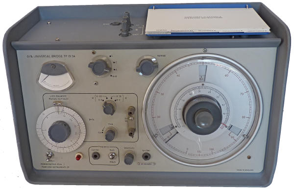
The TF131A general purpose impedance bridge is able to
measure resistance, capacitance and inductance with one tenth percent
accuracy. The bridge is balanced by a switched set of precision
resistors and a variable potentiometer for fine balance. It is housed
in a very substantial die cast aluminium casing. This model was first
made in 1966 and this one judging by the date codes (37/70 and 43/70)
of some of the internal components was manufactured towards the end of
1970.
Resistance measurement 3 milliohms to 110 meghohms in 8 ranges with the bridge being supplied with a DC supply.
Inductance measurement 0.1 microHenhies to 110 Henries in 7 ranges with the bridge being supplied with a AC supply of 1kHz or 10kHz. Q values of between 0 and 310 can be measured.
Capacitance measurement 0.1 picoFarads to 110 microFarads in 7 ranges with the bridge being supplied with a AC supply of 1kHz or 10kHz. D values of between 0.0005 to 3 can be measured.

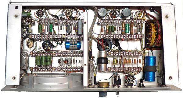
The chassis is revealed by removing the screws holding the top cover and those on the underside of the casing. In this view (from Left to Right) can be seen: small box containing neon/photo resistor chopper circuit, EF86, Coarse and Fine balance assembly, 12AX7, metal rectifier with function switch above, 12AT7 with output transformer and D/Q switch above, 6X4 and mains transformer with balance meter above.
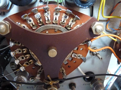
The left hand section of the underside of the chassis is normally covered with an aluminium screen.
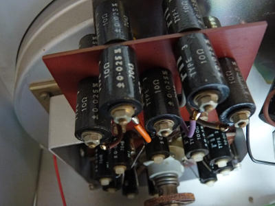
The switched set of 10 ohm precision resistors. There are ten of these 0.025% resistors and ten 100 ohm 0.025% resistors on the rotating switch assembly below. The Range switch is coupled via a wire drive to the windows on the dial of the instrument.

