Type 6040
serial number 215776
serial number 215776
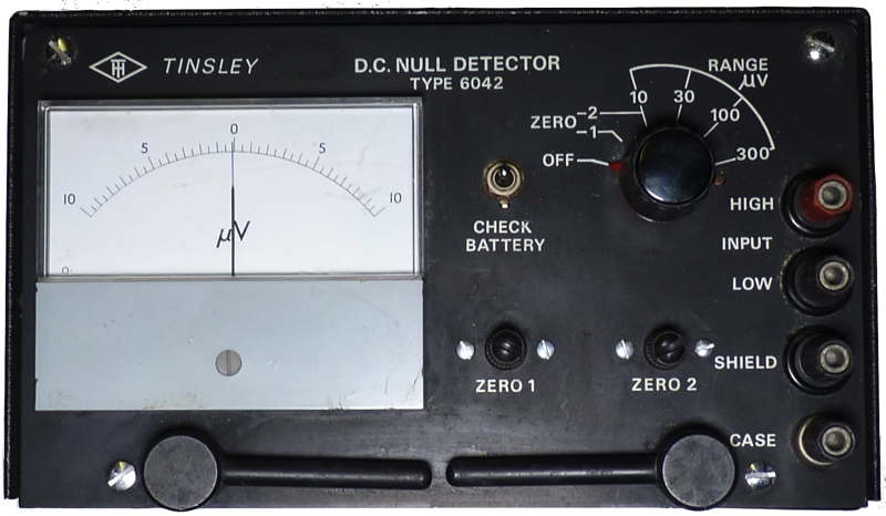
Tinsley DC Null Detector
type 6040 H. TINSLEY & CO., LTD.Werndee Hall, South Norwood,
London, SE 25 UK
1969
This is a DC Null Detector suitable for use with portable instruments.
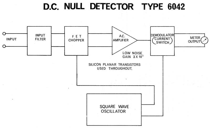
The circuit uses an F.E.T. chopper operating at 35Hz followed by an AC
amplifier with negative feedback. The output is reconstituted by means
of a current switch. An input filter is provided and consists of l0uf
capacitors and 3.9K ohm resistors. Zero setting is by means of two
controls, one for setting the zero with the input short circuited and
the other for setting the zero with the input open circuited.
Specification
Sensitivity: 10-0-l0uV full scale deflection upon 4 inch meter.
Ranges: 10, 30, 100, 300 uV
Input resistance: l4,000 0hms
Resolution: 1uV. in 10,000 Ohm source resistance.
Noise: 0.l5uV. peak to peak.
Response time: 2.5 secs.
Series mode rejection: 54 db
Temperature coefficient: 0.3uV per degree C
Overload recovery time: from l.0V input 3 secs
Power Source: PP7 dry battery
Current Drain: 6mA
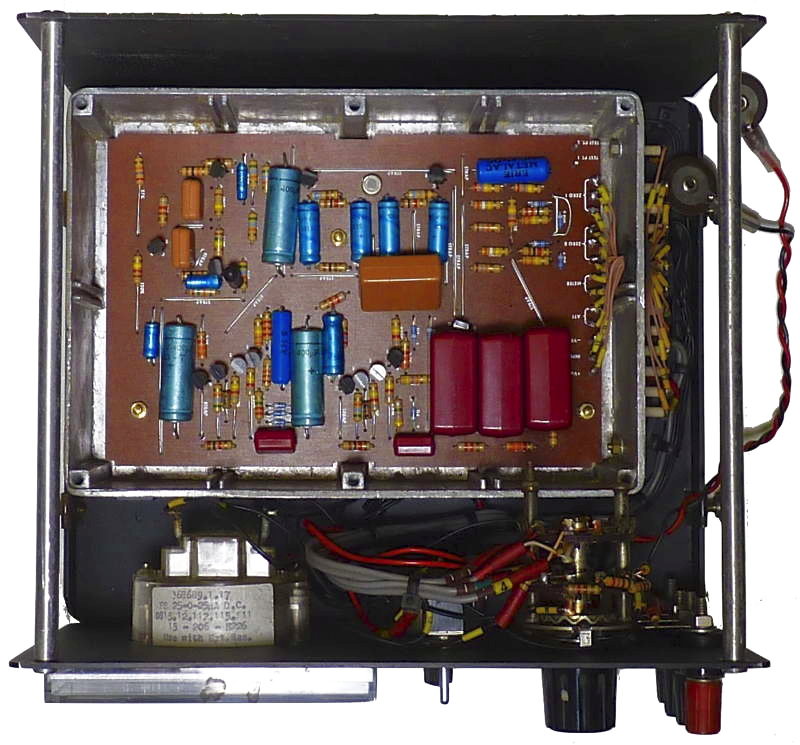

Inside view with
cover of shielded box removed and an advert from 1970
I was given this instrument which formed part of a collection of many instruments collected by Bob Evans by his daughter Alice Kirby. Although it gave indications when powered up I was unable to zero the instrument. Fortunately it came with an operating manual which included a circuit diagram. I noticed that the the wires to the printed circuit board had been removed and re soldered at some time and there was a rather long screw on the range switch which did not seem to be as it might have left the factory. I found that the diagram was in error [for example R1 was 1.8 K not 2.7K] and in tracing out the wiring to the switch established that some of the resistors on the diagram are not mounted on the printed circuit. I discovered that the board had been removed to insert a link short circuiting the 22 ohm resistor associated with the ZERO 1 potentiometer [see diagram below]. As the voltages appearing at the bases of the demodulator seemed to be low I changed the transistor on the amplifier output, though this seemed to have little effect upon the biassing and DC levels.
After a lot of seemingly fruitless
checking I put it all back together it can be zeroed and it appears to
work correctly. I have removed the PP7 battery clip and made a shaped
wooden retainer to keep a PP9 battery in its
place.
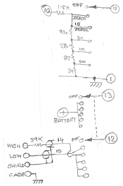
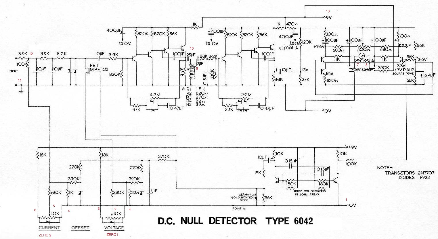
The diagram reproduced here is an amended
version of that in the manual and includes the variations I have found
and [in red] the wire and terminal numbers on the board.

