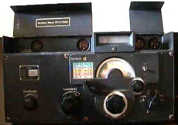
Ex German Army 'Koln' E52b-1 Ln21000-s s/n 462647 Dark grey steel and aluminium case, black knobs all valves and adjustments accessible from outside by lifting covers.
Crystal controlled communications receiver with side contact valves. used for radio direction finding 10x RV12P 2000 2xRG12D60 1xMSTV140/60Z MZ6001 (vibrator) 1.5 to 25 MHz in 5 wavebands working Telefunken Germany 1942
This item was originally installed in a German army radio vehicle which as I remember was built and equipped to the same standard as the receiver. I believe that it was used as part of a radio direction finding system. My father used it regularly between the end of WW2 and 1983. The output transformer has gone open circuit and I wired another alongside it as a temporary repair many years ago. I have hand drawn circuit diagram which may be more complete than the one shown here Simplified Circuit diagram (76k GIF file)
Have a look at: http://www.laud.nofor general information on this and other German WW2 radios. This Norwegian site of Helge Fykse which has some good pictures of the internal construction. Another useful site: http://www.armyradio.com
It is a Telefunken design and became available around 1943. It was
meant for short wave communications in the army and for governmental
organisations. It is thought that about 2500 of these sets were made
between 1942 and the end of WW2.
Dimensions 24.1 cm high, 44.6 cm wide and 36.9 cm deep.
Weight 42.8 kg (94 lbs.).
Power 110-220 V. a.c. or 12 V. battery (selector switch on back).
Frequency ranges
( Range I ) 1.5-3 MHz, white
( Range II ) 3-6 MHz, red
( Range III ) 6-10 MHz, yellow
( Range IV ) 10-17.6 MHz, blue
( Range V ) 17.6-25 MHz, green .
Valves10x RV12P 2000, 2xRG12D60, 1xMSTV140/60Z MZ6001
(vibrator)
All the RV 12P 2000 (side contact) valves can be reached by lifting the two covers at the front top of the receiver. The tubes can be removed by means of a special tool that is screwed into the valve base. These covers give access to various adjustments and test points.More than 16 million RV 12P 2000 valves were produced during WWII. These were extremely versatile: for use as triodes and diodes the anode and grids were strapped together and for a double diode triode the suppressor grid acting as one of the the diode anodes and the screen grid as the triode anode.
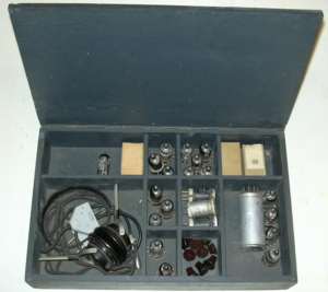
I also have the spare parts box which contains headphones, several valves and a vibrator.
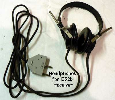
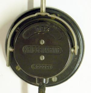
These are the headphones which belong to the radio,The fabric covering the steel spring headband is frayed. I am at a loss to know why they are labelled Kriegsmarine (see second picture).
A novel feature of the tuning mechanism is a projection system
which displays the frequency with great resolution.The effective length
of the scale on each of the five wavebands is two metres! The shaft of
the
tuning capacitor carries a glass disc on which the calibration for
each frequency range has been deposited by photographic means, like
on a microfilm. A small lamp illuminates the disc from behind and the
frequency the radio is tuned to is projected by means of a lens
system onto a ground glass screen above the conventional dial.
The glass discs were individually calibrated for each receiver. A
spare disc is included in the rear of the set. A built-in spare lamp
can be brought into operation by turning the slotted screw below the
ground glass screen should the operating lamp fail .
How much is it worth?
There are not a great number of these around and it has been
suggested that one in working order which has not been modified is
worth in excess of �1000. I saw that a rather nice looking one was sold
on Ebay in 2014 for €2210

