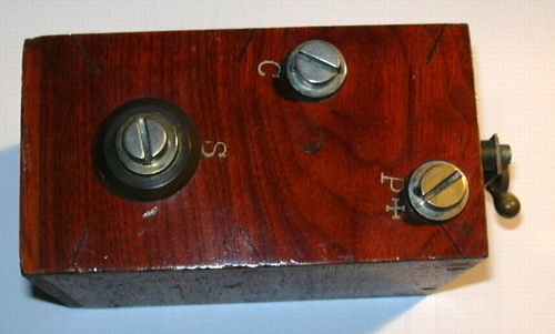
Induction Coil I do not know what this was used for, it came
as an unexpected part of an auction lot. It appears to be part of some
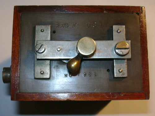
larger apparatus since only the front and top (as shown here) of the
unit are polished. The ebonite panel is stamped "REG.No.381 No 7988".
Adjacent to the C terminal is an ellipse enclosing what looks like 8TH.
The windings are encased in a solid block of wax and are continuous. I
am now pretty sure that it is part of an early spark transmitter. I
believe it to be a British spark induction coil from a military WW1
field telegraph set. This
site gave me the idea:trench
transmitter
Since then I have seen a picture of a transmitting receiving set sold
by Gamages of Holborn prior to 1914 which included an almost identical
adjustment lever and contact arrangement. This was illustrated and
described in the BVWS Bulletin (vol.25 no.1). A similar item is shown
in the centre of a photograph of a pre World War 1 radio station on
page 237 of "Radio Radio".
Peter Norris who viewed this page has provided some
interesting information about the automobile buzz coil. He has a Model
T ford coil and provided this link
They were housed in a modular box 130 x 80 x 50mm, not including the
contact breaker mechanism on the end
and the connections were to 3 button shaped terminals, one on the end
and
two on one long side. This enabled the coils to be slid into a coil
box.
It was common to have one coil per cylinder as this avoided having to
distribute the HT. The engine was instead fitted with a low voltage
'distributor' which cycled the LT current to the appropriate coil at
the
right time. The armature was very light so the frequency of operation
was
high - hence the term buzz. The spark on mine can be drawn out to over
�
inch so they are pretty powerful devices and some care is sensible.
He suggests that "P+
is battery positive, S is spark plug and C is the LT contactor (battery
negative). You could try 6V between P+ and C and expect up to 4 amps to
flow with activity at the contact breaker. Try that momentarily and if
no
vibration, disconnect, open the points adjuster, reconnect and then
bring
the points into contact which should start the armature vibrating.
Throughout this you should arrange a spark gap between S and C using a
short
length of stiff wire - gap about 1mm - to unload the secondary winding.
Not much to go wrong with them apart from points burnt and eroded away,
condenser failure which would exacerbate points burning or an open
circuit
in the secondary. An avo meter check should give a good indication of
health but you could go ahead and try it with maybe an car headlamp
bulb in
series in case there is a short present."

