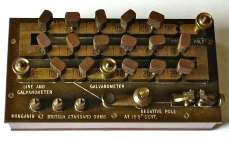
Pye (ex WD) No.3363 Resistance Bridge Polished wood casewith Bakelite panel. brass plugs for resistance selection and brassterminals.Designed for line testing, two 10 ohm arms and one variable100 ohm arm. Manganin BS ohms @ 15.50Cworking Cambridge UK 1916
The top is made of thick ebonite supporting undercut brass blocks shaped to accommodate sixteen interchangeable brass shorting plugs which have ebonite handles. The brass blocks are connected to resistance coils of thick wire to reduce the effect of heating when passing large currents. The coils are of manganin resistance wire, the resistivity of which does not change appreciably with small changes of temperature. The accuracy of such a resistance standard may be taken as 0.25%.
Resistance is inserted by removing a plug, which, when in place, short-circuits the resistance. This device is configured as a Wheatstone bridge, with terminals and key switches for a battery and galvanometer. An unknown resistance can be clamped between the terminals provided and the bridge balanced (when no current flows through the galvanometer) with an equal resistance of unshorted coils between 0.1 and 100 ohms.
As can be seen from the simplified diagram above the bridge is equipped with two 10 ohm fixed arms and one variable one enabling resistance values up to 100 ohms to be measured. Recently I came across this site which has some similar devices http://www.fairmile.fsbusiness.co.uk/otherequipment.htm which gives a clue as to how it might have been used for telegraph communication.
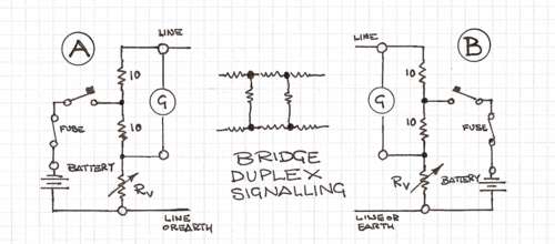
The simplest way of signalling with which we are all well acquainted is our house doorbell which comprises a battery, push button, a pair of wires and electric bell. This principle is fine for one way communication but the need for simultaneous two way signalling over the same conductors (Duplex working) is a little more complex. One of the solutions utilises the property of the Wheatstone bridge at balance to have no voltage across the local galvanometer or sounder so that it will only respond to signals from the remote station.
For this to work it is necessary to accurately balance out the resistance of the line and the instrument connected to its far end. The line which may be several miles long could have a loop resistance (there and back) of several tens or hundreds of ohms. The many insulators on which it is suspended also have a finite leakage resistance which although possibly tens of megohms each are in parallel across the line. I have indicated this on the above diagram by the ladder arrangement of resistors between the two stations A and B. It is not necessary to have two conductors between the stations if the ground is sufficiently damp and conductive to provide an adequate path. The loop resistance will vary depending upon the temperature, humidity, pollution and perhaps earth conductivity. This means that some form of regular adjustment is needed to ensure the proper working of the installation.
Although this resistance box together with a galvanometer similar that shown here galvo.html could form part of a duplex signalling installation it seems more likely that it would have been used for testing and setting up such systems.
Pete Andrews has a 1942 edition of Military Engineering Part IV Demolitions which includes test instructions and sketch for the "Coil, resistance, 100-ohms". The sketch matches my photo. It was included along with a "Detector Quantity and Intensity MkI" (which he has), and "Box, Safety test cell S", in the "Box, testing and jointing" which was used to test the integrity of electrical demolition circuits. By 1942 a new 200 ohm version was in circulation, and the 100 ohm model was rated as obsolescent. He thinks it's a Mark IV or Mark V, because the instructions state the Mark III version didn't have the 3 pillars for spare wire reels in the bottom left corner. There were earlier editions of the book Military Engineering "Mining and Demolitions", though he doesn't have copies, which may help identify the exact mark number.
History of Pye see: www.pyetelecomhistory.org/

