No.L-159799
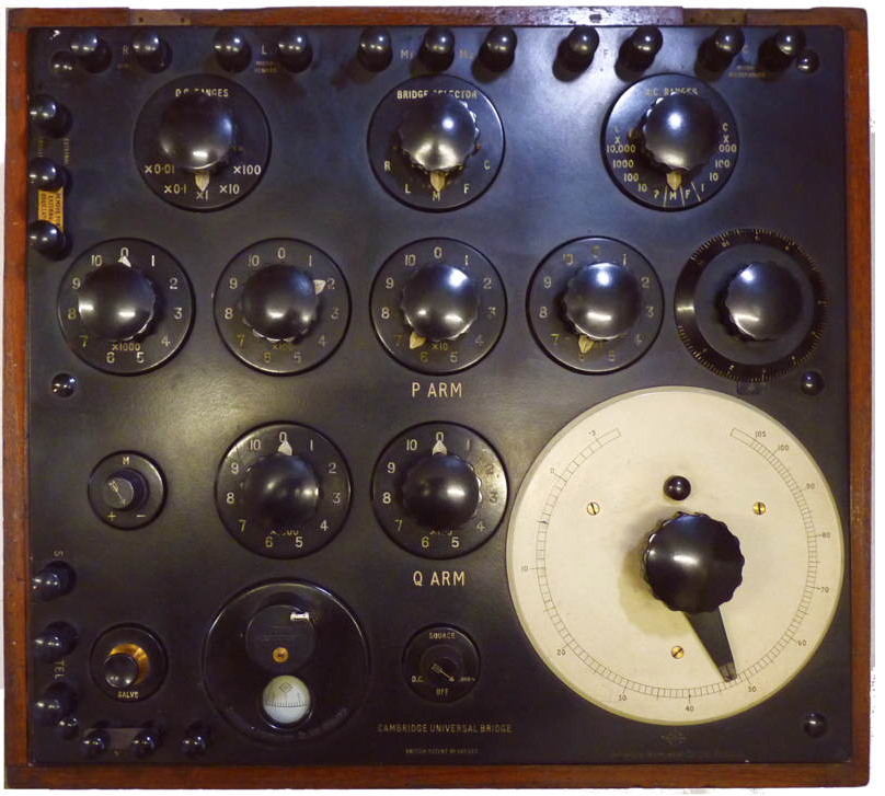
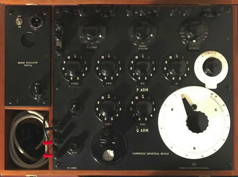
Cambridge Instruments universal bridge (patent 449623) housed in a substantial mahogany box with a compartment for battery (I assume two bell cells) and an earpiece. This is one of many instruments collected by Bob Evans and given to me by his daughter Alice Kirby. The instrument has been modified to include three terminals and a brass link so that an external null balance meter could be connected in place of fitted the 'unipivot' meter. The underside of the lid has a single large paper sheet with brief instructions for use. This had been water damaged and the protective celluloid sheet had yellowed over the years, I ironed the paper flat prior to scanning it and producing the PDF file Here. The back of the sheet had been rubber stamped with the date and place of manufacture, but tantalisingly the actual year is indistinct, however the large grey capacitor has a date code which suggests week 44 1947. Cambridge Instrument Company Ltd, Muswell Hill, London. UK, 1947?
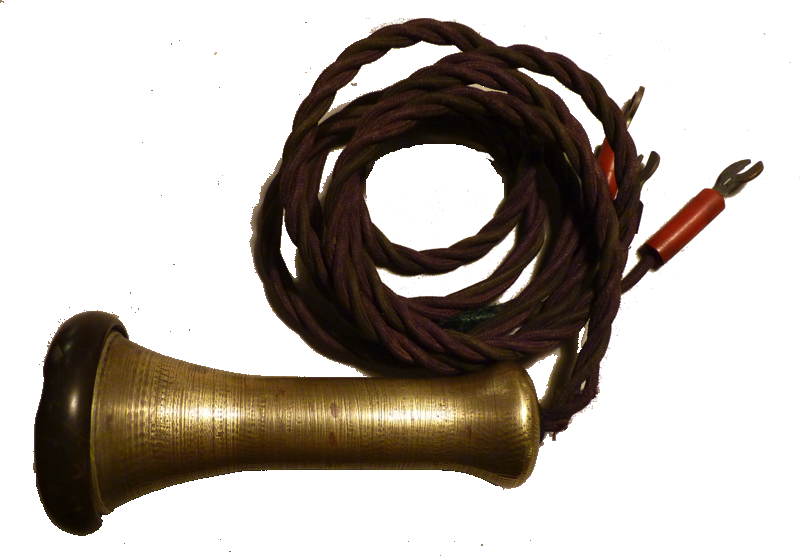
Earpiece for
detecting null balance on AC measurements.
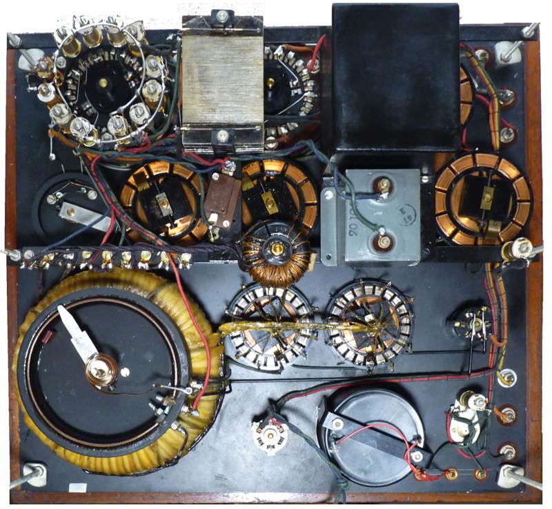
I discovered that the instrument had an interesting way of
producing an sinusoidal (I guess) signal for the bridge, this was
housed in the black steel box which can be seen next to the grey
capacitor in the picture above. This was no longer functioning and it
seems that someone had unsuccessfully tried to get it working in the
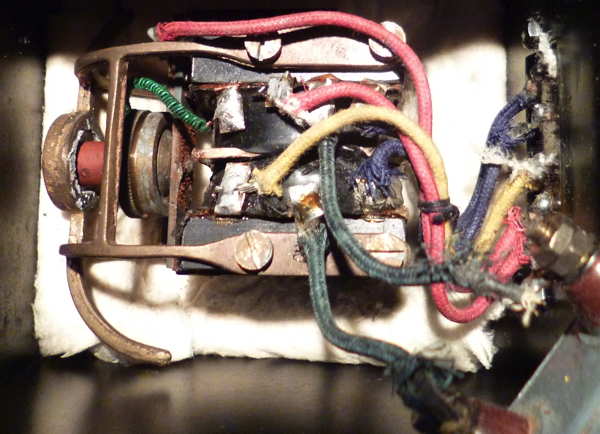
past. As can be seen from the picture it is essentially a buzzer
with
three coils where the contacts have been replaced with carbon granules
set between two carbon discs housed inside a cylindrical brass housing.
A capacitor was connected between two of the windings.
oscillator and
rubber stamp
How does it work?
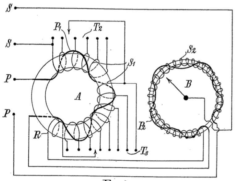
The patent application of December 1934 is headed "Improvements in and relating to electrical measuring instruments"
A variable mutual inductance for bridge measurements of inductance,
resistance, frequency and capacity comprises primary and secondary
windings in toroidal form wound over the whole length of a core of
non-magnetic material and provided with means for obtaining a finely
stepped variation of the mutual inductance. The windings are wound on a
tapered flat core which is afterwards bent into ring form, or the
cross-section of the core may be circular or elliptical. The mutual
inductance unit may be housed with a high-frequency generator in a
universal bridge testing set.; An inductometer comprises two toroidal
windings A, B connected in series, the primary winding part P1 being
tapped for connection to adjacent bridge arms, the secondary part S1
being tapped and provided with a reversed section R. The other part
windings P2, S2 are also variable in respect of their mutual
inductance, the degree of variation of the parts P2, S2 being equal to
one step of the coarser adjustment made with parts P1, S1.
This is a more modern version owned by Mathew Neale which includes a power supply and 1000Hz oscillator [presumably transistorised]

