Evershed & Vignoles "Wee" and Series 3 Megger
Evershed & Vignoles Megger series 3 patent 400728 (also
known as the "Wee" megger) and an earlier model once owned by
John Ward, X-Ray engineer, of Lichfield Staffs given to me by his son
in law, John Bagshaw. These
are very common instruments, every electrician would have needed one of
these well constructed robust insulation testers. From what I can
gather the change in naming took place around 1950 when this model and
the larger instruments were renamed. I have had the series
3 model
since 1966 when I bought it second hand for � 5, sadly today they are
still only worth about � 10 Later versions of the series 3 have AC
generators with diode rectification (see below). both
working.
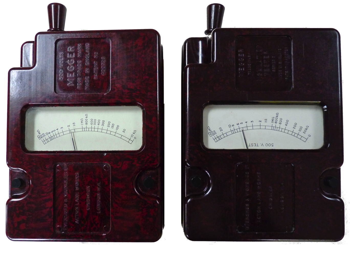

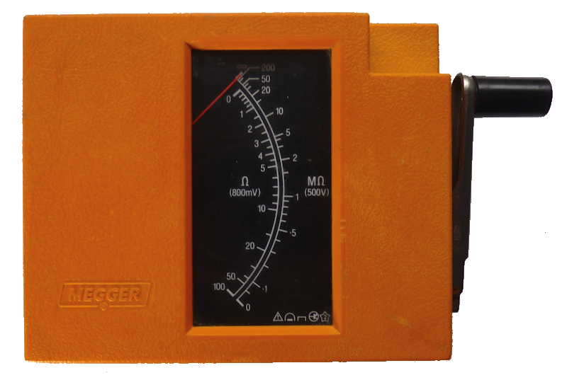
"Wee" on left and Series 3 model on the
right [open images in new window for enlarged version]
The "Wee" has two wirewound 100kΩ
resistors and a 0.1mFd capacitor. The series 3 has Welwyn carbon film
resistors, two 100kΩ, two 75kΩ and 0.1mFd capacitor with a series
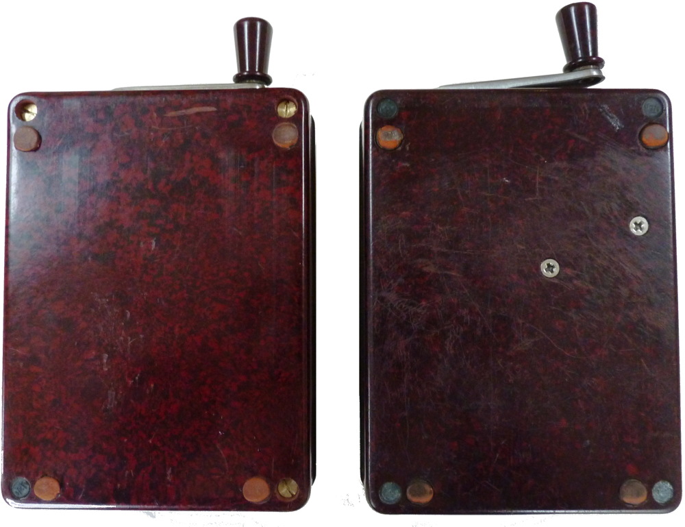
47kΩ resistor. Note the helical gears and nylon drive wheel on the
later instrument.
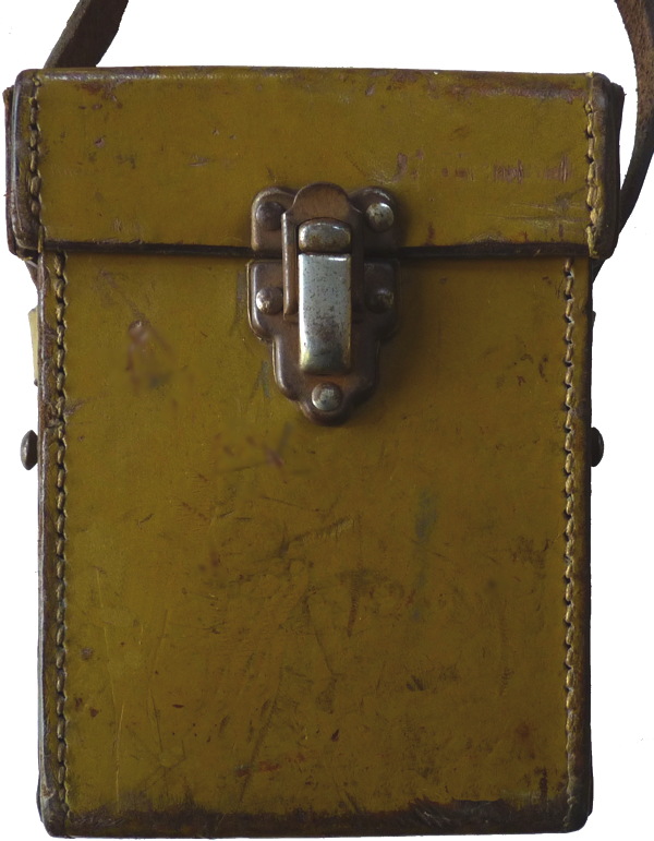
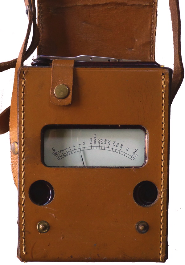
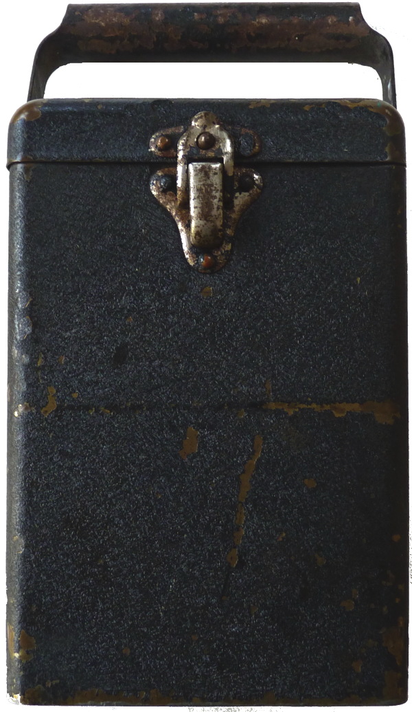
They were often kept in leather or
brass cases.
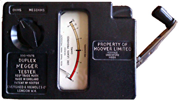
The "Megger" instrument for measuring the insulation resistance of
electrical devices was introduced by the British firm of Evershed and
Vignoles in 1903. The name comes from the fact that the insulating
resistance of a properly-designed appliance is in the range of tens and
hundreds of megohms. The crank on the end powers a DC generator
connected to a specially-designed meter. GB patent number 400728 was
granted in 1933. Connections are made by depressing the spring loaded
black buttons and slipping the bare end of the connecting wires into
the holes on the sides.
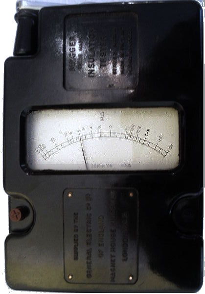
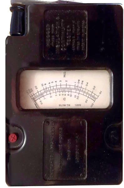
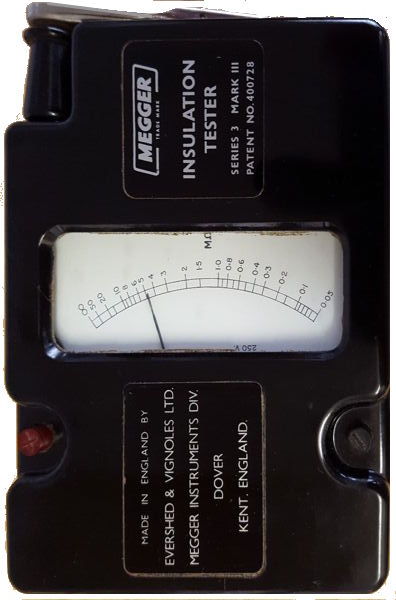
Three
series 3 Mk3 insulation testers in black casings.
On the left one supplied by General
Electric Company (GEC), in the centre a dual range instrument and on
the right one made in the Dover Factory after 1966
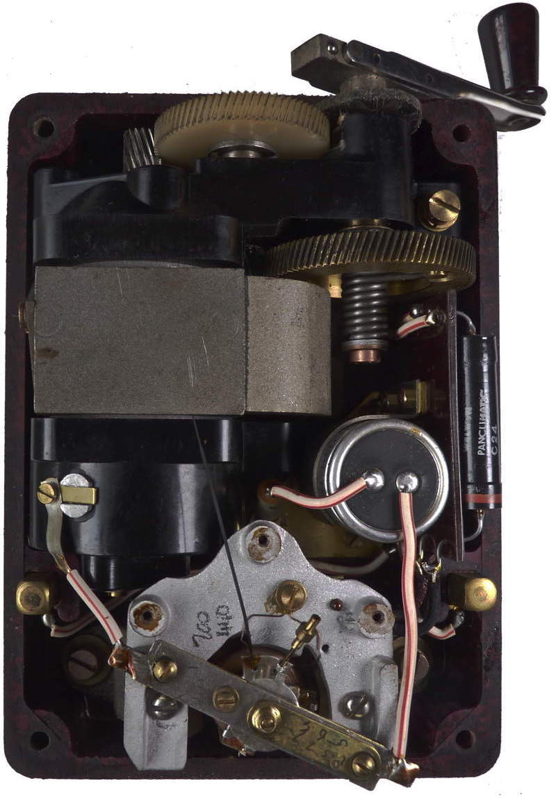
Angus Jamieson sent me this picture of the inside of his
megger. He discovered that one of the meter deflection coils and one of
the wire wound resistors was open circuit. He fortunately had another
meter movement and dismantled the dial assembly completely to replace
the deflection coil, re-attach springs etc. The faulty wire wound
resistor was bypassed with two metal film resistors in series. The
capacitor is an aluminium cased Dubilier made 0.1mFd 1500V DC Test. It
is connected in series with a 47K ohm resistor across the generator
terminals. Both wire wound resistors are 100K ohms. He has kindly
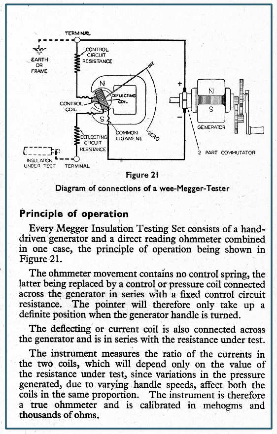
scanned a copy of the 1947 edition of the handbook (5Mb PDF) which you
can download by clicking on the image showing the diagram of
connections (which does not show the above mentioned capacitor and
resistor). These were included on later models to improve the output
voltage.The pages when printed out can be reassembled into a booklet.
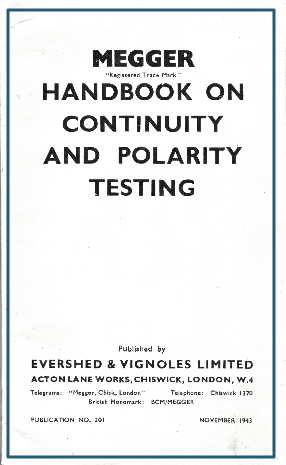
Also a scanned a copy of his 1943 edition of the handbook on continuity
and polarity testing (4.8Mb PDF)can be downloaded by clicking on the
second image.
Dorian Stonehouse has
covered the operation, disassembly andrepair of his instrument here
evershed
vignoles_wee megger series3_
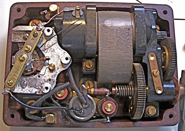
Note the slipping clutch on the main gear wheel to limit the
voltage output.
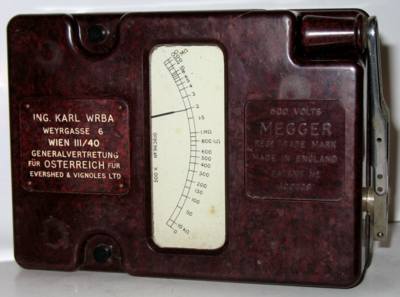
Selyem Toth Sandor from Hungary has
sent me
some
pictures
of his meggers [serial number 963610] one of which I reproduce here.
You will see that it is the same as mine but has been labelled by
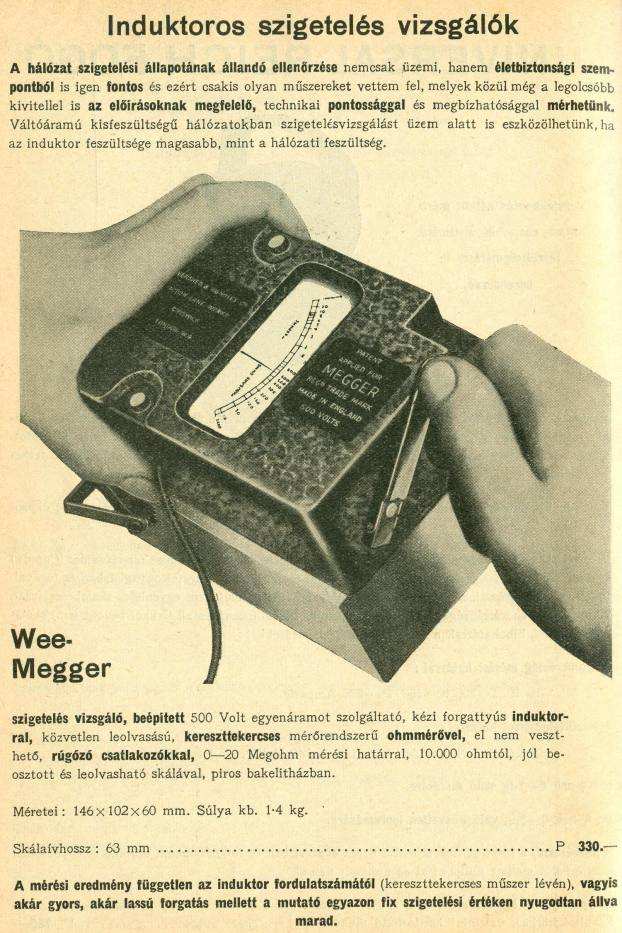
the Austrian agent for Evershed and Vignoles.He also sent me this copy
of a Hungarian leaflet.I don't know how old this leaflet is but you may
be able to
discern that this picture was made before the patent was granted. S T
Sandor has over 700 radios see here:

Versions
This little megohm meter proved very popular and
over the years Evershed and Vignoles made many improvements and used
the same format to manufacture related instruments. 100, 250 and
500Volt versions with 20, 50 or 100MΩ ranges as well as custom
designed models such as this one
were made for a
particular client were made. Biddle in
America marketed a labelled version but called it the "Midget" megger,
and subsequently manufactured them.
It is
worth noting that the scale plates of these instruments were
individually calibrated and printed and thus not interchangeable. Many
were made to meet the requirements of the
military for example:
Air Ministry 5G/152- 250V 20MΩ and
5G/1621- 500V 50MΩ
Admiralty AP5057 - 250V 20MΩ and AP12924- 500V 50MΩ
Instruments bearing these numbers
were
probably made prior to 1956 (Nato codes introduced about this time)
Others were made for other firms, this one
has a specially moulded front panel and a hinged protective cover for
the meter. The light green in colour is only a surface finish which has
worn away to reveal the more traditional brown Bakelite beneath.
(picture supplied by Bill Toynton)
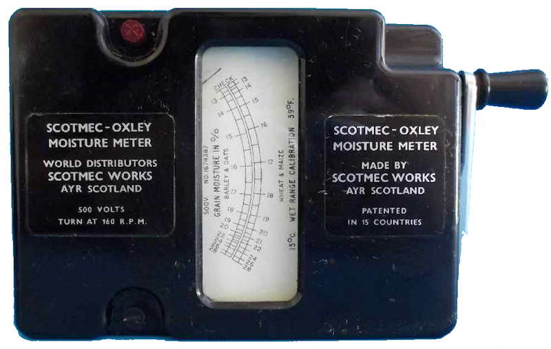
The versatility and utility of the Wee
Megger led to it being used for other purposes, in this case in
conjunction with special probes as a moisture meter for testing grain.
This instrument probably dates from the mid 1960s:
Until 1950 [I
think] the internal design stayed much the same as it was in 1932.
About this time the whole range was renamed and the 'Wee megger' became
a 'Series 3 megger'. Mine is, I believe, a MK2
version. The series 3 MK3 version introduced in 1960 incorporates an
AC generator and a diode voltage multiplier to provide the test
voltage. I wonder why it took so long for this change to happen as
E&V were granted a provisional patent [783998] in 1946: "Permanent
magnet generator system" Perhaps the magnetic materials of the time
were not adequate?
The series 3 version was discontinued sometime during the late
1960s to be replaced by the WM4 WM5 and WM6 all of which are powered by
an AC generator and include a
continuity range. Click on image for information in this range
WM5
How to use
These instructions were originally included
with the megger (I do not have the original):
"To test insulation
between circuit and earth, connect one terminal to the circuit and the
other to a good earth. To test between a winding and its frame connect
one terminal to the winding and the other to the frame. For a test
between conductors connect one to each terminal. Having made the
connections turn the handle at about 160 r.p.m. The resistance is then
indicated on the scale.
Further instructions are given in publication No. 200."
NEVER TOUCH THE TEST LEADS WHILE THE MEGGER IS BEING USED and
make sure that the item you are checking is deenergised, discharged and
isolated before using the megger. Normal insulations should read
infinity. Any small resistance reading indicates the insulation is
breaking down. The circuit or item you are testing may have
considerable capacitance and retain an electrical charge after testing.
After you make your connections, you apply the test voltage for 1 min.
This is a standard practice to enable relatively accurate comparisons
of readings from previous tests. The insulation resistance reading
should drop or remain relatively steady. This is because electrical
insulation materials exhibit capacitance and will charge up during the
course of the test. After 1 min, you should read and record the
resistance value.
What affects insulation
resistance
readings?
Apart from
dirt and damp insulation resistance is temperature-sensitive. When
temperature increases, insulation resistance decreases, and vice versa.
A common rule of thumb is insulation resistance changes by a factor of
two for each 10 degree C change. So, to compare new readings with
previous ones, you'll have to correct your readings to some base
temperature. For example, suppose you measured 100 megohms with an
insulation temperature of 30C. A corrected measurement at 20C would be
200 megohms (100 megohms times two). It is also worth bearing in mind
that as time goes by the quality of insulating materials gradually
deteriorates (especially at elevated temperatures).
How does it work?
The construction and connections are
shown below. The moving system consists of two coils, the "control
coil" and the "deflecting coil"-rigidly mounted at an angle to one
another and connected, in parallel across a small generator, with
polarities such that the torques produced by them are in opposition.
The coils move in the air gap of a permanent magnet. The control coil
is in series with a fixed control circuit; the deflecting coil is
connected in series with a fixed deflecting circuit resistance and the
resistance under test. If this last is infinitely high no current flows
in the deflecting coil and the control coil sets itself perpendicular
to the magnetic axis, the pointer indicating "Infinity." A lower test
resistance allows current to flow in the deflecting coil and turns the
movement clockwise. The control torque produces a restoring torque
which progressively increases with the angular deflection, and the
equilibrium position of the movement is attained when the two opposing
torques balance. A resistor capacitor snubber circuit is connected
across the generator teminals to smooth the DC output. Note that these two items are not
shown on the typical iMegger instruction leaflets.
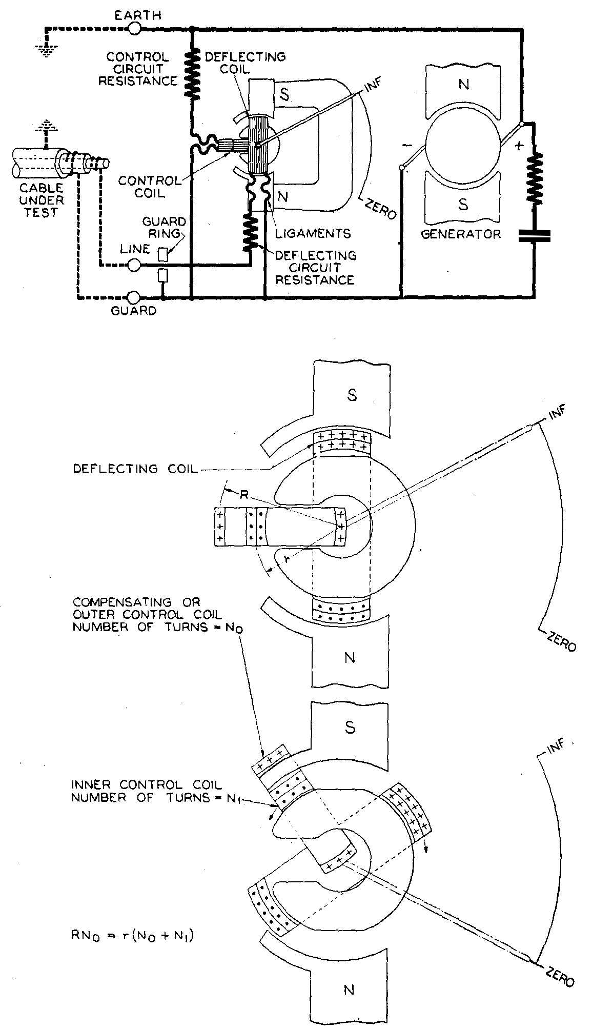
The control coil is actually in two parts, in series, the
outer
part being a compensating coil. The two parts are arranged with numbers
of turns and radii of action such that, for external magnetic fields of
uniform intensity, their torques cancel one another thus giving an
astatic combination.
The instrument has a small permanent magnet d.c. generator
developing 500 V DC. (Other models have 100, 250, 1,000 or 2,500 V
generators). The generator is hand-driven, through gearing and a
centrifugally controlled clutch which slips at a predetermined speed so
that a steady voltage can be obtained.
The guard terminal (if fitted) acts as a shunt to remove the
connected element from the measurement. In other words, it allows you
to be selective in evaluating certain specific components in a large
piece of electrical equipment.
For example consider a two core cable with a sheath. As the diagram
below shows there are three resistances to be considered.
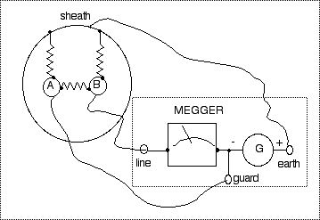
If we measure between core B and sheath without a
connection
to
the guard terminal some current will pass from B to A and from A to the
sheath. Our measurement would be low. By connecting the guard terminal
to A the two cable cores will be at very nearly the same potential and
thus the shunting effect is eliminated.
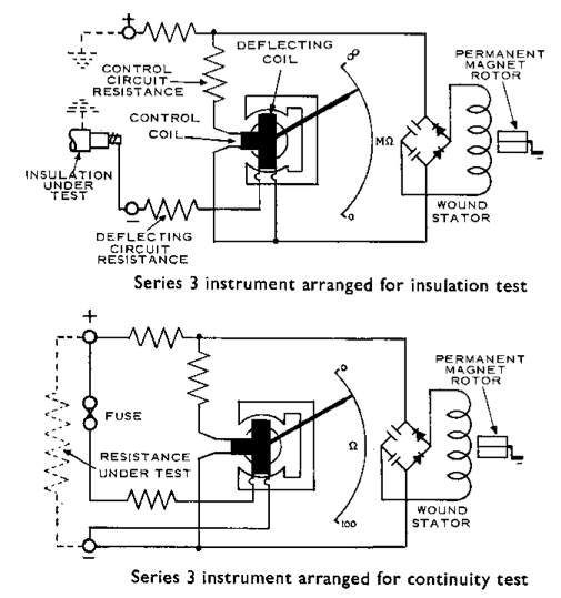
The series 3 Mk 3 (from about 1960) have AC
generators with diode rectification and voltage doubling. Combined
insulation and continuity measurong instruments were also made:
Other insulation testers work on the same principle though
the
voltage required may be obtained from a battery operated inverter or a
motor driven generator. see this example.
For more information on Evershed and Vignoles early insulation testing
equipment see: here.
Evershed & Vignoles Ltd of Acton Lane Works,Chiswick
were taken over by AVO Ltd. Avocet House, 92-96 Vauxhall Bridge
Road,
London, SW1. AVO was a member of the Metal Industries Group of
companies. Though known for their Avometer general purpose
multimeter
(see below), they made a wide range of test gear including valve
testers. The Acton Lane works closed down at about that time - around
1986. The current range of products can bee seen at: https://uk.megger.com
The firm Megger Ltd is now based at: Archcliffe Road,
Dover,
Kent,
CT17 9EN, United Kingdom.
For hand driven generators, Meggers and other insulation
testers click here

