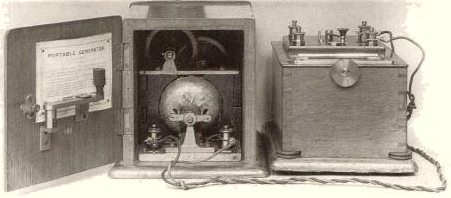
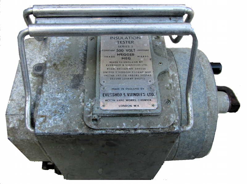
Original Evershed and Vignoles Hand Generator and ohmmeter.
Background
Telegraphy became a commercial success with the advent of the railways and those responsible for the design and upkeep needed to know about electricity. This was one of the factors which led to the birth of the term 'Electrical Engineer' as opposed to Civil or Mechanical engineers. In 1871 the Society of Telegraph Engineers and of Electricians was founded and published some rules in 1882 [see below]. The Society was the forerunner of the Institution of Electrical Engineers [IEE] which was founded in 1889.
In 1881 Joseph Swan started his own company, Swan Electric Light Co, and began commercial production of filament lamps and within a few years the popularity of electric lighting soared.
Rules and Regulations for the Prevention of Fire Risks Arising from Electrical Lighting 1882
"THESE rules and regulations are drawn up for the reduction to a minimum, in the case of electric lighting, of those risks of fire which are inherent in every system of artificial illumination, and also for the guidance and instruction of those who have, or who contemplate having, electric lighting apparatus installed on their premises.The difficulties that beset the electrical engineer are chiefly internal and invisible, and they can only be effectually guarded against by "testing," or probing with electric currents. They depend chiefly on leakage, undue resistance in the conductor, and bad joints, which lead to waste of energy and the dangerous production of heat."
These requirements, though not obligatory at the time, led to the growth of a new industry, the design and manufacture of portable easily used electrical instruments for the measurement of voltage, current and resistance. It was on the latter (in particular high resistance or 'leakage') that Evershed and Vignoles concentrated and for which they became famous.
Leakage
The resistance [commonly called insulation resistance] between current carrying conductors, or from live conductors to earth, will result in a leakage current. This current could cause deterioration of the insulating material, as well as involving a waste of energy. A leakage path to a conducting surface could expose people to an electric shock. In the case of telegraph or telephone lines it would result in signal attenuation. Insulation resistance is normally several orders of magnitude greater than that of the conductors carrying the electrical current. It is normally determined by applying a stable voltage between the conductors and measuring the current. The dial of the ammeter involved would be calibrated in Megohms [million ohms]
No electrical insulation is perfect, electrical insulation starts to age as soon as it's made and the resistance starts to fall. Temperature extremes and / or contamination, cause further deterioration. The insulation resistance of many materials is decreases as the voltage applied to it increases. Also when temperature increases, insulation resistance decreases, and vice versa. A common rule of thumb is insulation resistance changes by a factor of two for each 10 Degree Celsius change.
What is insulation resistance testing?
After connections are made, the test voltage should be applied for 1 minute. [This is an industry standard that permits relatively accurate comparisons of readings from previous tests.]
During this interval, the resistance reading should drop or remain relatively steady. On large systems the insulation resistance will steadily decrease. On smaller systems the reading will remain steady because the capacitive and absorption currents drop to zero faster than on larger systems. After 1 minute the resistance reading should be recorded.
Acceptable values of insulation resistance depend upon the equipment being tested. Historically, many electricians use the somewhat arbitrary standard of 1 megohm per kV.
Foundations of the firm
Goolden & Trotter, was founded in 1885 and it was here that Walter Thomas Goolden developed several designs for dynamos. When Mr. Trotter retired from the firm in 1893 it was amalgamated with that of Messrs. Easton and Anderson, under the style of Easton, Anderson and Goolden. Mr. Goolden took charge of the mining work of the firm in the North of England.
Back in 1888 whilst electric lighting was rapidly growing in popularity, Sidney Evershed was working for Goolden & Trotter in a department that specialised in domestic electrical installations. To verify the safety of those installations, the company needed a reliable and convenient method of testing insulation. However, at that time, insulation resistance could only be measured in a laboratory, and the measurements were carried out at low voltages, typically a few volts.
Evershed knew from his researches that testing at such low voltages gave unsatisfactory results, and that to ensure the safety of an installation, it was essential to test the insulation at its working voltage or higher. He also knew that the laboratory techniques for measuring insulation resistance were totally unsuitable for use on site.
His response was to develop the world's first direct-reading ohmmeter, which comprised a small permanent magnet suspended at the centre of, and controlled by, two coils at right angles to each other. One coil was connected directly to the voltage source energising the ohmmeter, the other was connected to the same voltage source via the insulation under test. This arrangement meant that the results obtained were independent of the voltage. Evershed energised his ohmmeter with a hand-cranked generator, similar to the type in use at the time for ringing telephones. The instrument proved to be so successful that Evershed patented it. Goolden & Trotter started to manufacture and market it in 1889.
On the 5th February 1895, Sidney Evershed and Ernest Vignoles, another Goolden & Trotter director, purchased the instrument department from that company and set it up as Evershed & Vignoles Limited in premises at Westbourne Park in London where the business was located until it was moved to The Acton Lane Works, Chiswick, London in 1903. The firm was taken over by AVO Ltd. Avocet House, 92-96 Vauxhall Bridge Road, London, SW1. AVO was a member of the Metal Industries Group of companies. Though known for their AVOmeter general purpose multimeter see here, they made a wide range of test gear including valve testers. The Acton Lane works closed down at about that time - around 1986. The current range of products can be seen at: http://www.megger.com/ The firm Megger Ltd. is now based at: Archcliffe Road, Dover, Kent, CT17 9EN, United Kingdom.
The insulation testers made by Evershed & Vignoles were given the name Megger, and on May 25, 1903, the company registered the word Megger as trademark number 254820
For many years, the James G. Biddle Company in Pennsylvania (now solely owned by Megger Ltd.), was the U.S. importer of Megger products and they also manufactured equipment under their own name, many of which were based upon the Evershed and Vignoles designs.
Hand generator - Evershed's patent.
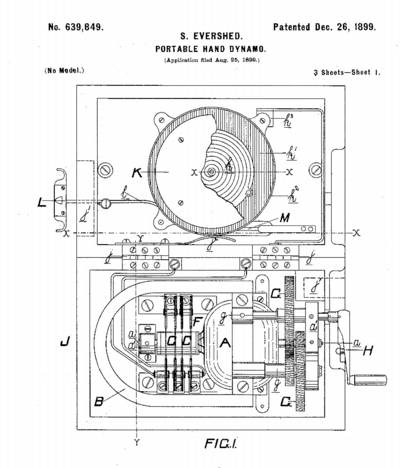
The generator was originally designed by W.T.Goolden of Goolden & Trotter and it was used separately from the instrument itself to obviate interference from the permanent magnet fields of the generator. Evershed improved upon the generator as can be seen from this patent application of 1899. (US patent 639849) a small part of which is reproduced here:
"Be it known that I, SYDNEY EVERSHED, a subject of the Queen of
Great
Britain and Ireland, residing at London, England, have invented a new
and useful Improvement in Portable Hand-Dynamos, (for which I have made
application for Letters Patent in Great Britain under No. 1,758,
bearing date January 25, 1899,) of which the following is a
specification.
This invention relates to portable hand dynamos, such as are used for testing
purposes or for firing electric fuses
or the like purposes, where a small current of high electromotive
force can be utilised; and it consists in an improvement whereby the
frictional resistance to rotation (of importance in such small
appliances) is reduced to a minimum both in the armature-bearings and
in the commutator, the current is collected with highest electromotive
force, the hand 'which is made collapsible when not in use and is then
in a protected position, and connection to any instrument or object, at
a reasonable distance from the generator, is rendered easy and rapid
without the use of loose wires, which may be mislaid, and without any
binding-screws projecting from the portable box containing the dynamo.
Figure 1 is a plan of the box, with
the lid open, containing the dynamo in the body of the box and the
winch-handle ready for operation issuing therefrom and the connection
device in the inside of the lid." If you want to read more and to
view other patents try this link www.google.com/patents
When Evershed & Vignoles took over the manufacture, and raised the
voltage to 200 d.c. from the original 120V. The lower voltage was
probably to test installations at the working voltage, commonly 110V at
that time, but it was then thought that twice the working voltage would
be a better test, which is what we do today, with 500V. d.c. test for
supply voltage around 250 Volts.
The Ohmmeter
A true ohmmeter measures the quotient of volts and amperes, but many simple instruments merely measure the current through the unknown resistance, assuming that the voltage remains constant during the test. Such instruments should be called resistance testers rather than ohmmeters. Multimeters [such as the AVO meter] use this principle on the resistance ranges.
From the beginning Evershed and Vignoles insulation testers had a meter with a voltage coil and a current coil combined in the movement. This was the most important, and at the time, unique feature of their insulation tester.
The early meters worked on the principle of moving a pointer by the combined fields of separate voltage and current coils thus enabling power or resistance measurements to be made with only one instrument. They used fixed coils at right angles to each other and there was a magnetised needle at the pivot end of the pointer. There was no problem with coil connections since they were fixed and there was no control spring. The needle doesn't come to zero until the test terminals are shorted and the generator operated. The movement relied upon the work of Ayrton and Perry who in 1881 invented and coined the words of Voltmeter and Ammeter.
These early insulation testers had a couple of drawbacks, the generator had to be kept away from the meter as the stray magnetic field from it could affect the magnetic needle of the meter and over time the strength of the magnetic needle weakened. To counteract the effect of any stray magnetic field the operator were advised to take the average of two readings, one when the generator handle was turned in one direction and a second when it was turned in the opposite way.
William Edward Ayrton (1847 - 1908) English engineer and inventor, with his colleague John Perry (1850 - 1920) invented many electrical measuring instruments. In these, a permanent magnet and a moving coil and the use of an ingeniously devised flat spiral spring (as used in modern analogue meters) which yields a relatively large rotation for a small axial elongation.
Evershed & Vignoles made an instrument with a double moving coil, one for voltage and one for current. They were fixed together, but not at right angles. The pointer was fixed to the coil assembly and the coil connections were ligaments, not hairsprings since the only influence on the coils was that of a powerful permanent magnet. This arrangement got over the gradual loss of magnetisation which the previous instrument suffered from. It also enabled the generator and meter to be combined into one instrument as it was no longer necessary to obviate interference from the permanent magnetic field of the generator. The first combined testers of this type were made in 1903 and patented in 1904.
These instruments had two massive bar magnets with pole pieces at both ends, so that one end did for the moving coils and the other provided the generator field.
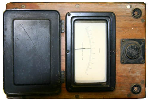
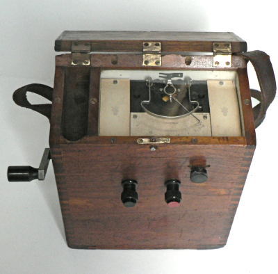
The following picture (from Instruments of Science: An Historical Encyclopaedia by Robert Bud and Deborah Warner (December, 1997) - Garland) shows an early Evershed and Vignoles insulation tester but has no indication of the date. On p.89 of Sir David Salomans' book, 'Electric Light Installations, Part 3' published in 1894 there is a picture of such an instrument and its hand generator connected by 'curly' single conductors..
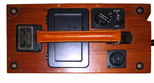
Original Evershed and Vignoles Hand Generator and ohmmeter.
Generators of this type were also being manufactured after the firm moved to Acton in 1903. The instructions printed on the lid of one of these meters are reproduced here:
PORTABLE TESTING SET
EVERSHED'S PATENT
INSTRUCTIONS FOR USE.
Adjust the Ohmmeter until the bubble is in
the
centre of the spirit level.
Place the generator not less than 18 inches away from the Ohmmeter and
couple its terminals to the terminals G1 G on the Ohmmeter.
Couple the mains to be tested to the "LINE" and "EARTH" terminals of
the Ohmmeter. Turn the Generator handle steadily in either direction at
any speed above 110 revolutions per minute, and the Ohmmeter index will
point to the resistance under test.
When making tests in the neighbourhood of dynamos and generally when
very accurate results are required two observations should be made,
first when the generator is revolving in one direction and then in the
other. The mean of the two readings so obtained gives the value of the
resistance under test.
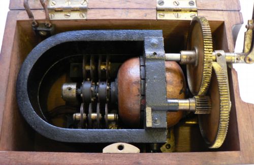
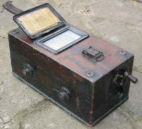
An Evershed and Vignoles 1900 Pattern Hand Generator [patent of 1899] from my collection [click on picture to see more].
As can be seen this generator has been constructed in
accordance with the diagram forming part of the 1899 patent and has a
cable reeling device on the underside of the lid, though other similar
machines are just equipped with terminals. The novel construction of
the commutator can be clearly seen. Both of these generators have been
likened to the hand driven magnetos used in early telephones, however
there are several important differences:
They machine have two stages of gearing [to increase the speed of
rotation and thus generate a higher voltage]
Have multiple poles
Have a commutator to provide a direct current output rather than the
low frequency required for bell ringing.
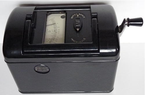
I have a copy of "Direct Current Electrical Engineering" by JR Barr published by Pitman in 1908 which describes "..........Sidney Evershed's ohmmeter or 'Megger'...." This is a combined instrument, the generator and the meter sharing the same magnetic field. Although there is no picture of the construction it would seem to be the same principle to that used on modern hand driven insulation testers. The generator part of these meggers is very similar to the stand alone generators. This method of construction was used by Evershed and Vignoles for maybe 60 years so it is often difficult to date such instruments. Though some owners have reported that the date of manufacture and calibration details can sometimes be found on the underside of the wooden lid.
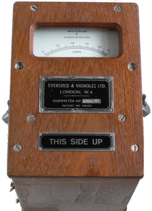
An early Evershed and Vignoles megger of the type first patented in 1906.
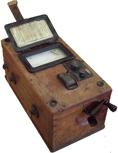
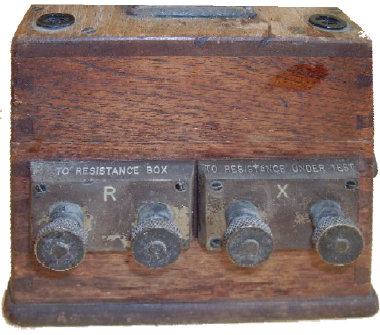
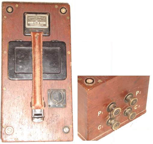
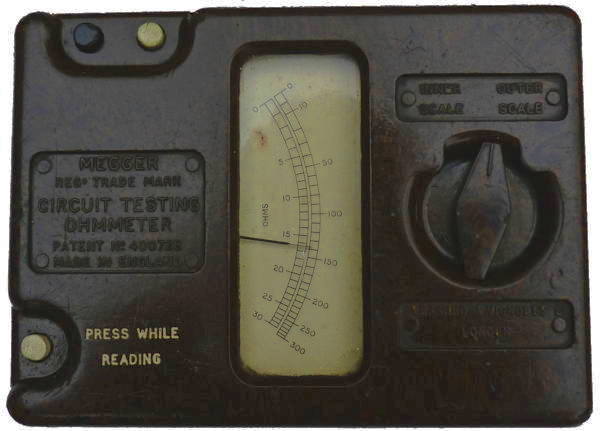
An early Evershed Bridge Megger. The side terminals are for insulation testing and the terminals on the end used for continuity testing.
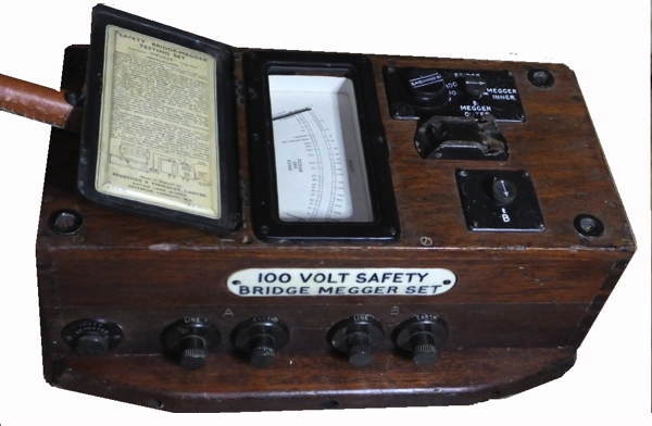
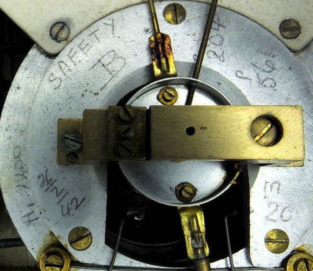
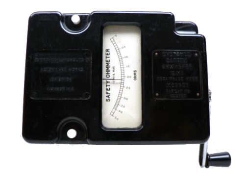
Mike Fooks provided this picture of a Safety Bridge
Megger (serial number 430471) which was made in February 1942
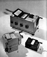
Changes over the years
The following picture has been taken from the 'Megger pocket book on insulation and continuity testers' dated 1960. They are described as Series 1, 2 and 3 as indicated on the illustration. The same basic constructions and principles were used for a wide variety of insulation, conductivity and continuity testers. Continuity testers are sometimes called Ducters [a term registered by Evershed in 1908], presumably a shortened version of 'conductor tester.' Earth Testers using the same housing and construction but equipped with four terminals were introduced in 1926. The earliest wooden cased combined meggers had a hinged top cover, on the later ones the top cover was held in place by four machined screwed rods an nuts. The 'Meg Tester' was a metal cased predecessor to the series 2 range of instruments, these date from 1923 onwards and the latter from about 1932. The series 4 range of instruments date from around 1954 onwards.
Originally the generators were all direct current (DC), but by using an alternating current (AC) generator with a rotating magnet it avoided the need for carbon brushes. The output of the generator was rectified with diodes and capacitors and limited by a silicon carbide stabiliser. This also meant that by using AC, voltage- multiplying circuits could be employed to give a choice of DC output voltages usually in the range of 50 to 1000 volts. This change took place as a result of a 1947 patent.
How old is my megger?
People regularly contact me asking how old their newly acquired instrument might be. I have tried to establish whether it might be possible to estimate the date of manufacture from the serial numbers. I have looked at information given to me by contributors and searched the internet and examined the entries on auction sites. From what I have been able to glean it would seem that the serial numbers start from a low number and increase over the years. There does not appear to be any kind of date code included in the numbers, though it seems likely that blocks of serial numbers were allocated for instruments of a particular type.
I have so far found 35 instruments and pieces of equipment [not exclusively meggers] where serial numbers have been given or are visible on photos. The earliest, an ammeter dated 1895 has a serial number 1656 and the latest, a megger has a serial number 2 606 230. By correlating the numbers with the dates for the various patents etc. I have produced this very rough guide to those manufactured at the Acton works between 1903 and 1986 or thereabouts:
9 000 after 1903
48 000 after1910
96 000 after 1919
170 000 after1928
260 000 after1935
430 000 after1942
800 000 after1950
1000 000 after 1954
2000000 after 1964
have a look HERE as well!
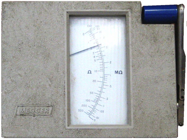
Evershed & Vignoles Series 3 Megger from my collection [click on picture for more information]
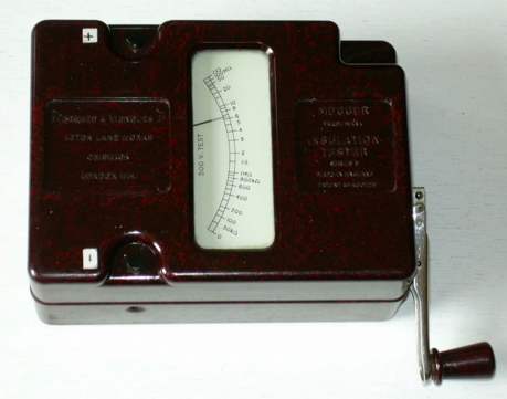 >
>Evershed & Vignoles Megger series 3 patent
400728 (also
known as the "Wee" megger) was introduced in 1932. This is
a very common instrument, every electrician would have needed one of
these well constructed robust insulation testers. These instruments and
their modern larger units are equipped with separate magnetic circuits
for the meter and generator. After 1947 the DC generator was abandoned
in favour of an AC one with diodes and capacitors to provide the
requisite test voltage. With the increasing availability of transistors
later models [in the 1960's] dispensed with the generator completely
and were battery operated, the required test voltage was generated
using a transistor oscillator and step up transformer although a more
modern form the WEE megger with a hand generator was produced for many
years well into the 1980s.
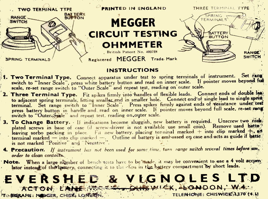
The crank powers a DC generator connected to a specially-designed meter. GB patent number 400728 was granted in 1933. Connections are made by depressing the spring loaded black buttons and slipping the bare end of the connecting wires into the holes on the sides.You will note that I have added two labels indicating the polarity of the terminals because I use it to check electrolytic capacitors.
How to use These instructions were originally included with the series 3 megger (I do not have the original):
"To test insulation between circuit and earth, connect one terminal to the circuit and the other to a good earth. To test between a winding and its frame connect one terminal to the winding and the other to the frame. For a test between conductors connect one to each terminal. Having made the connections turn the handle at about 160 r.p.m. The resistance is then indicated on the scale. Further instructions are given in publication No. 200."
NEVER TOUCH THE TEST LEADS WHILE THE MEGGER IS BEING USED and make sure that the item you are checking is de-energised, discharged and isolated before using the megger. Normal insulations should read infinity. Any small resistance reading indicates the insulation is breaking down. The circuit or item you are testing may have considerable capacitance and retain an electrical charge after testing. After you make your connections, you apply the test voltage for 1 min. This is a standard practice to enable relatively accurate comparisons of readings from previous tests. The insulation resistance reading should drop or remain relatively steady. This is because electrical insulation materials exhibit capacitance and will charge up during the course of the test. After 1 min, you should read and record the resistance value.
How does it work?
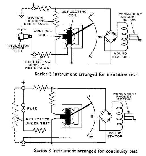
The construction and connections are shown below. The moving system consists of two coils, the "control coil" and the "deflecting coil"-rigidly mounted at an angle to one another and connected, in parallel across a small generator, with polarities such that the torques produced by them are in opposition. The coils move in the air gap of a permanent magnet. The control coil is in series with a fixed control circuit; the deflecting coil is connected in series with a fixed deflecting circuit resistance and the resistance under test. If this last is infinitely high no current flows in the deflecting coil and the control coil sets itself perpendicular to the magnetic axis, the pointer indicating "Infinity." A lower test resistance allows current to flow in the deflecting coil and turns the movement clockwise. The control torque produces a restoring torque which progressively increases with the angular deflection, and the equilibrium position of the movement is attained when the two opposing torques balance.
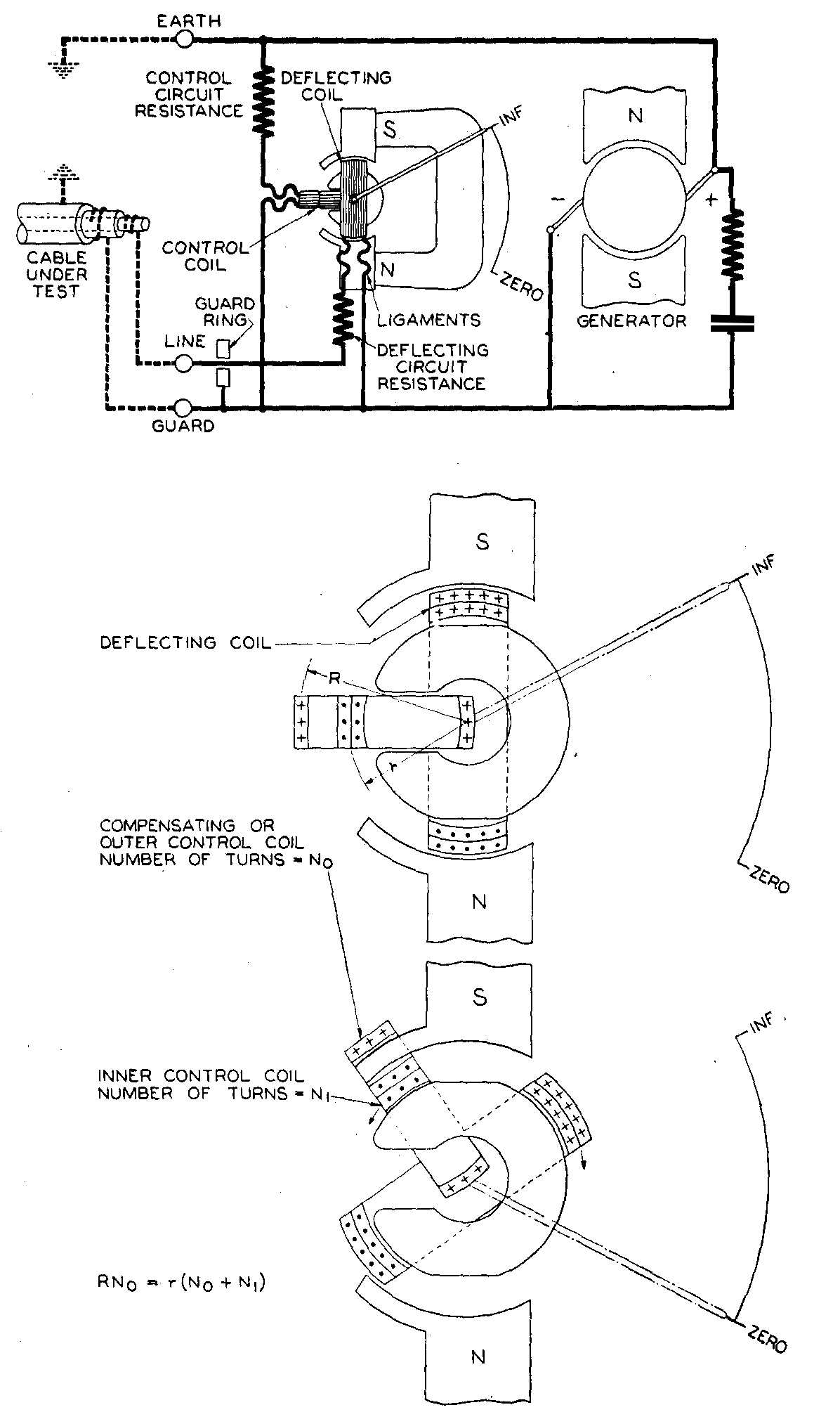
The control coil is actually in two parts, in series, the outer part being a compensating coil. The two parts are arranged with numbers of turns and radii of action such that, for external magnetic fields of uniform intensity, their torques cancel one another thus giving an astatic combination. Another refinement was an auxiliary coil in series with the voltage coil and moving over a horn shaped projection on one of the pole-pieces which enabled the scale to be more evenly calibrated.
The instrument has a small permanent magnet d.c. generator developing 500 V DC. (Other models have 100, 250, 1,000 or 2,500 V generators). The generator is hand-driven, through gearing and a centrifugally controlled clutch which slips at a predetermined speed so that a steady voltage can be obtained.
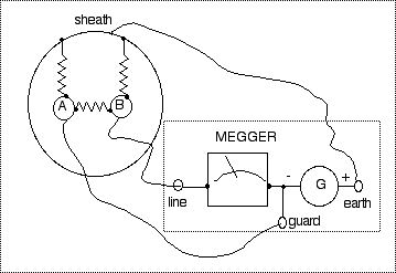
The guard terminal (if fitted) acts as a shunt to remove the connected element from the measurement. In other words, it allows you to be selective in evaluating certain specific components in a large piece of electrical equipment. For example consider a two core cable with a sheath. As the diagram shows there are three resistances to be considered. If we measure between core B and sheath without a connection to the guard terminal some current will pass from B to A and from A to the sheath. Our measurement would be low. By connecting the guard terminal to A the two cable cores will be at very nearly the same potential and thus the shunting effect is eliminated.
Other insulation testers work on the same principle though the voltage required may be obtained from a battery operated inverter or a motor driven generator. For more information on Evershed and Vignoles early insulation testing equipment see: here.
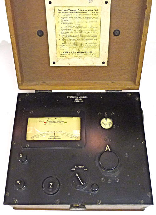
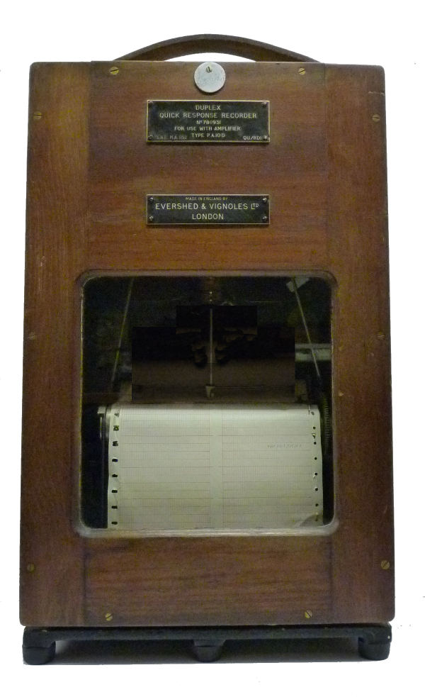
Combined Continuity and Insulation Testers Evershed & Vignoles also made combined units housed in the same casings as the Series 1, 2 and 3 housings. The Series 3 Mk111 tester incorporated an AC generator and a rectifier.
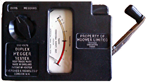
This is a series 3 combined instrument Duplex Megger Tester which seems to have been specifically made for the Hoover company.
(image provided by Wayne Sharman)
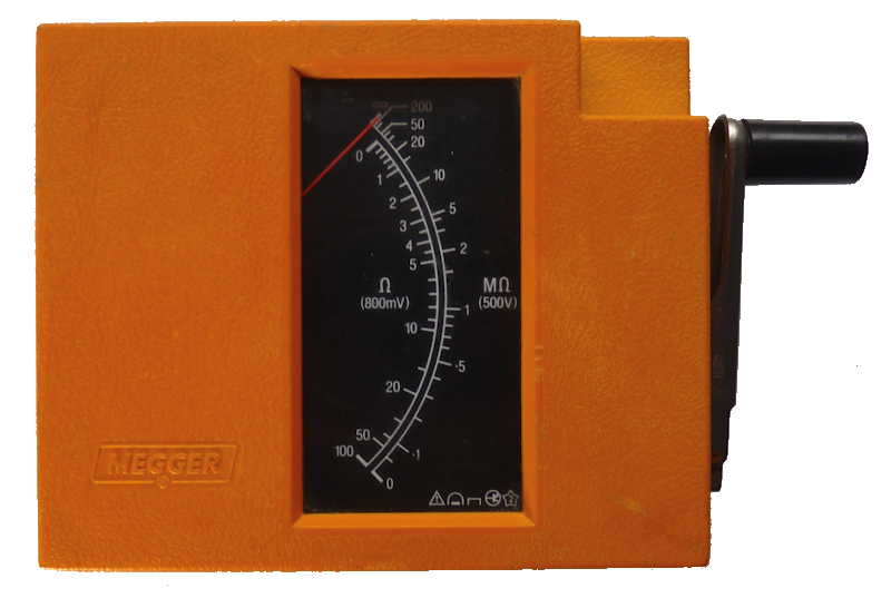
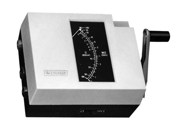
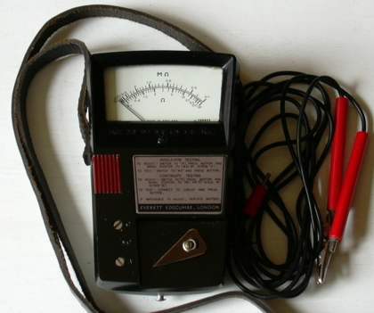
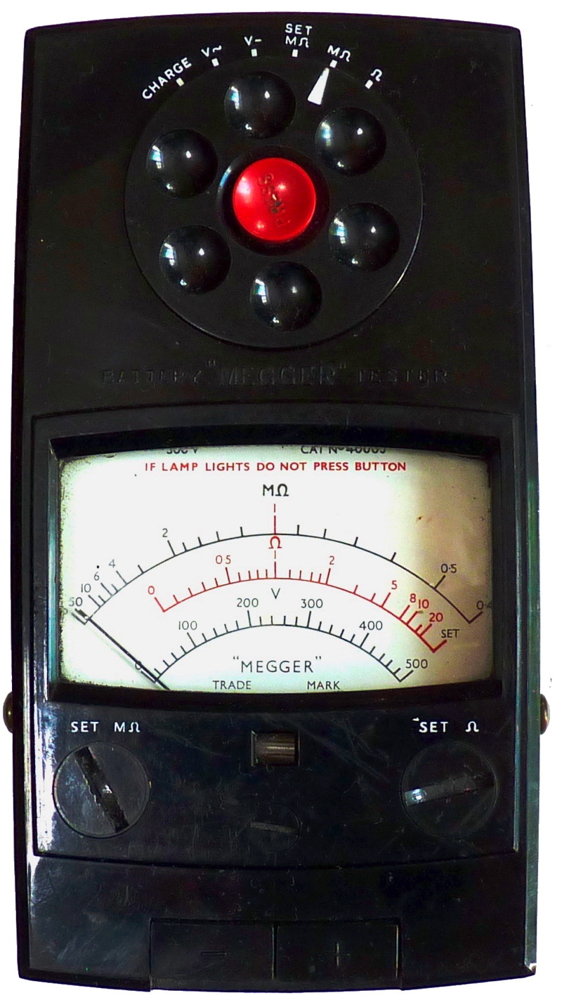
This is a low voltage ohmmeter [in my collection] of similar construction to the "Wee" Megger for more information click here.
The series 3 version was discontinued sometime during the early 1960s to be replaced by the WM4 WM5 and WM6 all of which included a continuity range.
WM4, WM5(made in 1987) and a WM6
Series 2 instrument
The series 2 instrument
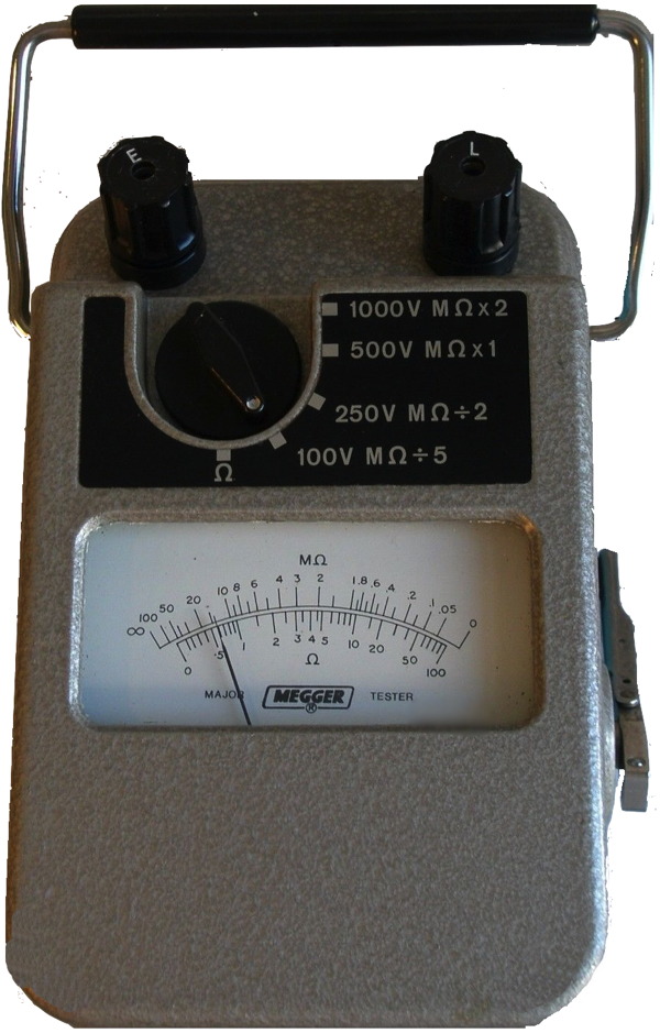
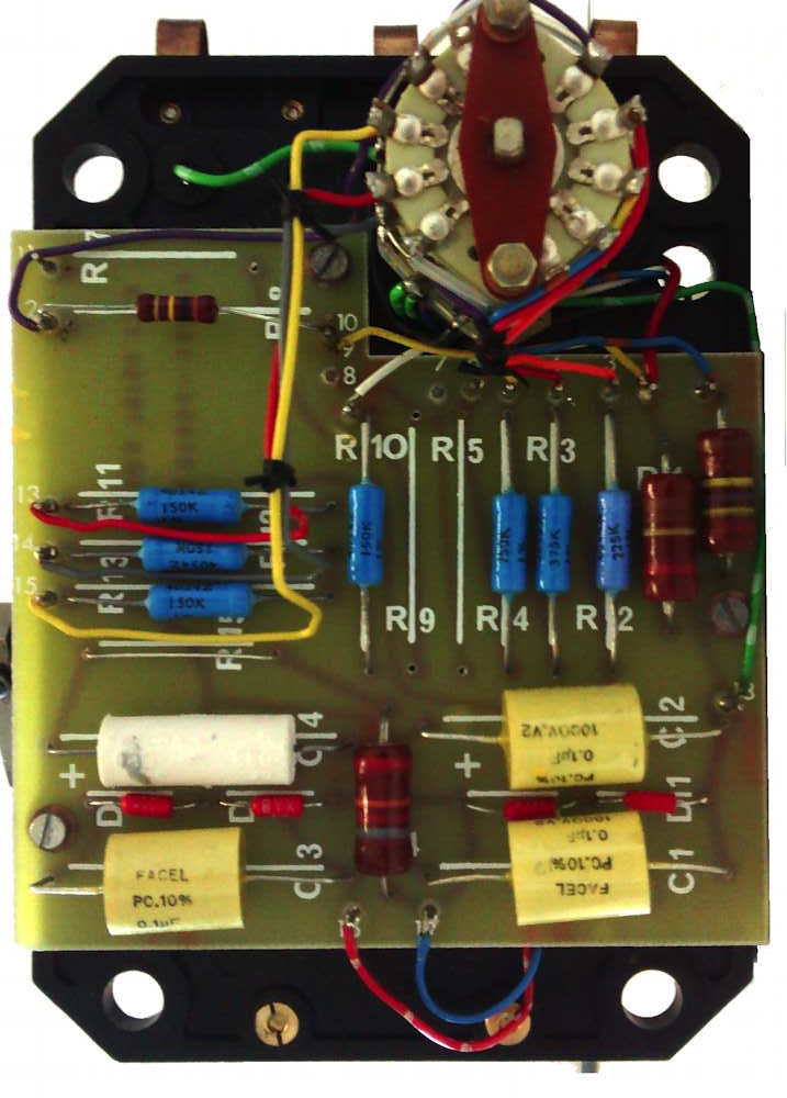
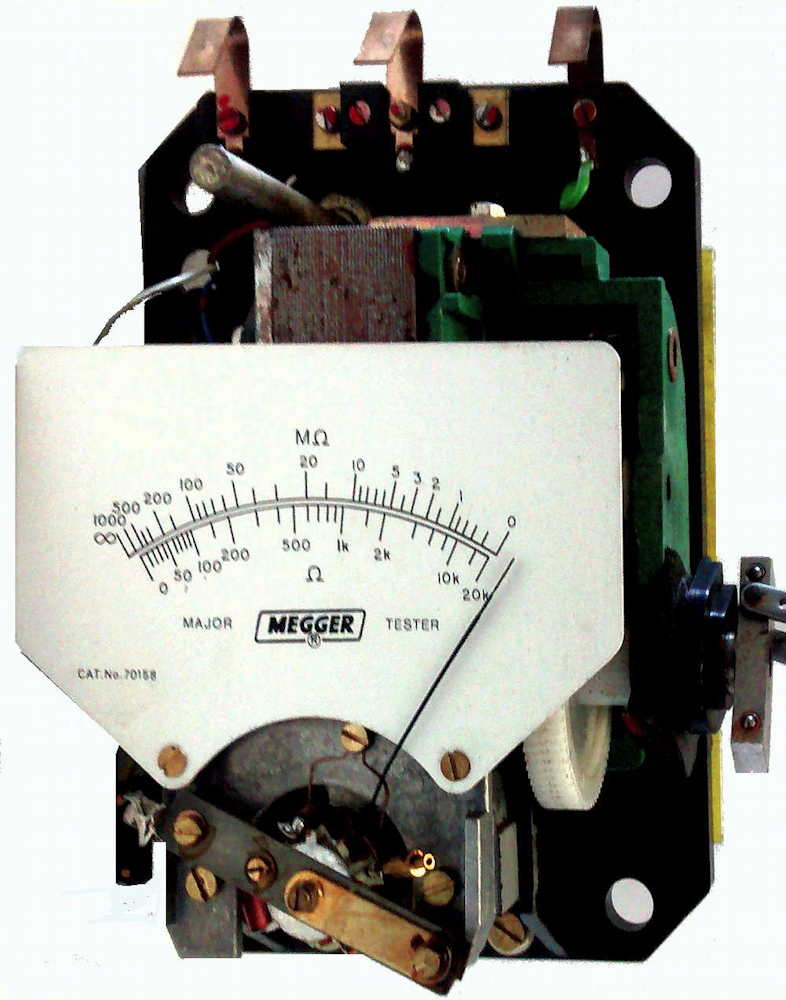
was superseded in 1963 by the Major range
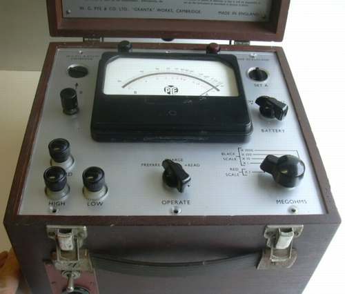
This is a series 1 earth resistance tester for testing earth loop impedance, probably dating from the late 1960's
This is a series 4 ohmmeter for testing earth loop impedance, for more information click here.
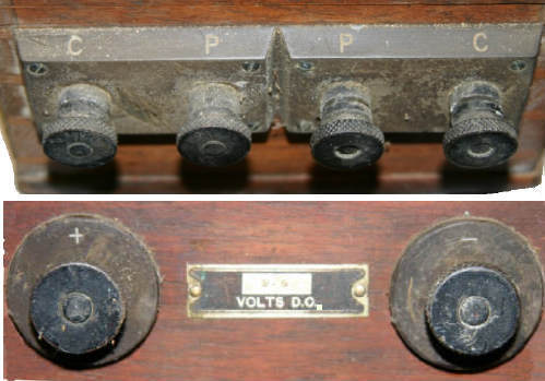
The DUCTER was part of a range
of BONDING TESTERS
typically used for checking earth bonding.
Power for the unit came from a bank of nife cells giving 1.3 volts at
about 10 amps. These are connected to the terminals at the opposite end
to those shown. The test probes comprise of 2 hand held plastic probes
each with 2 spring loaded prods. The probes are approx 8 inches long.
PROBE 1----red lead to P1 and black lead to C1
PROBE 2----red lead to P2 and black lead to C1
Instructions
Press the probes down firmly across the joint under test (ideally the P
connection would be closer than the C connections)
Current flows through the "C" circuit ,powers the control coil in the
movement and produces a potential difference (p/d) across the
resistance under test.
The deflecting coil is fed by the p/d developed by the external
resistance and is detected by the "P" prods.
This method of testing removes the need to compensate for volt drop
caused by the resistance in the test leads which could be similar to
the item under test!
Highly accurate and repeatable figures can be obtained.
This is an earlier version of the ducter shown above designed for a 2.5 volt supply.
Another refinement was an auxiliary coil in series with the voltage coil and moving over a horn shaped projection on one of the pole-pieces which enabled the scale to be more evenly calibrated.
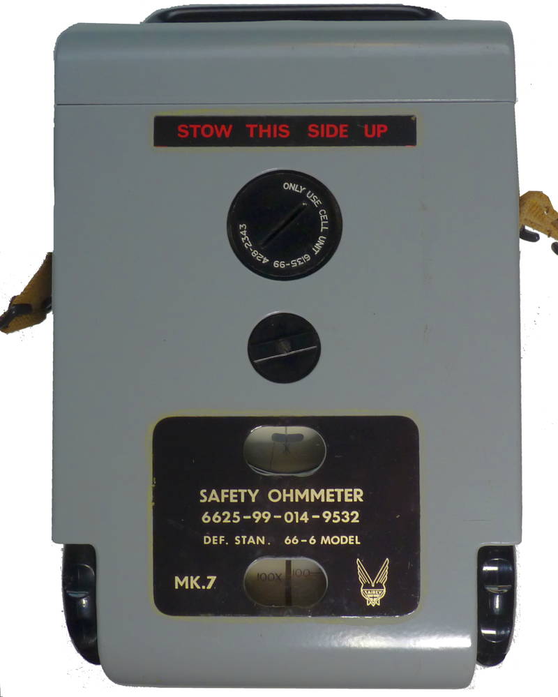
This is the principle of analogue insulation testers,(see:Megger , Safety Ohmmeter and Metrohm) but the voltage and auxiliary coils are combined into one but still move over the horn shaped projection. For more information see 'Electrical Measurements & Measuring Instruments' by Golding published by Pitman 1935
This is a battery powered instrument based upon the same principles used for testing the effectiveness of earth bonding on aircraft, for more information click here.
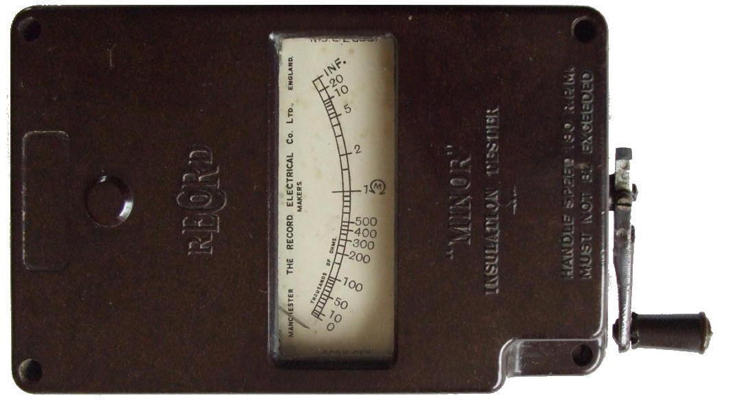
The Record
Electrical Co Ltd
who are perhaps better known for their
"Circscale" range of panel meters manufactured portable insulation
testers some of which were very simiar to the Evershed an Vignoles
models. One such instrument very similar to the series 3 range is shown
below. In 1955 Evershed and Vignoles acquired the Record Electrical Co
Ltd a firm which was started in 1911 by JW Record.
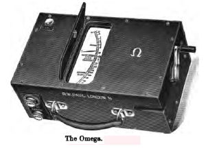
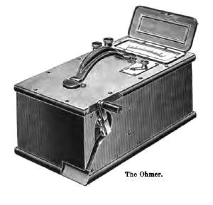
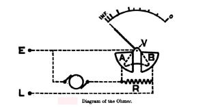
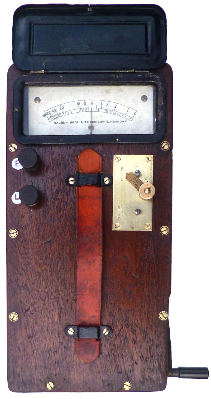
In Electrical Engineering by TC Baillie MA DSc AMIEE published by Cambridge University Press in 1915 there are descriptions and illustrations of several portable testing sets including the familiar wooden cased Evershed and Vignoles instrument described above. The other instruments described are the Omega manufactured by RW Paul which has a moving coil meter and separate generator mounted in the same enclosure. The Megohmmeter of Kelvin Bottomley and Baird which resembles the Omega but includes a divide by ten key to change the range of the instrument. The Ohmer made by Nalder Bros and Thompson is also a self contained instrument but unlike others has an electrostatic meter movement which made it the lightest instrument on the market at the time.
I have other insulation testing instruments in my collection which may be of interest [click on the pictures to see more information]
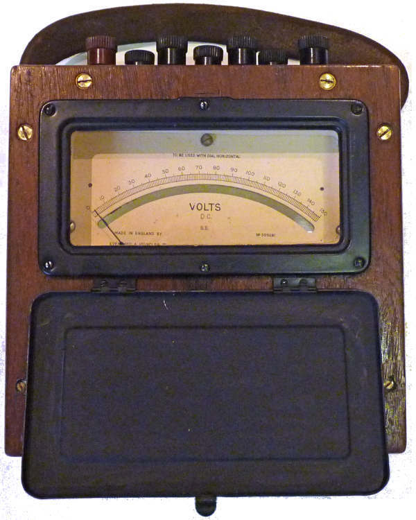
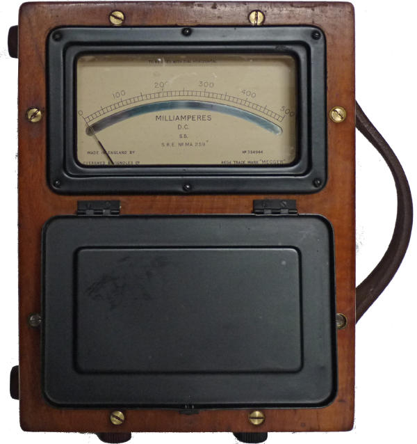
Over the years Evershed and Vignoles made a wide variety of electrical instruments and I have four other instruments which are illustrated here: [click on the pictures to see more information]
Links to other pages on this site about Evershed and
Vignoles:
Evershed and Vignoles time line
find
out how old your meter might be
E&V publication detailing 1951 product line
text file
A large file of the above including
illustrations This is a 24MB PDF file of a scanned copy.
Sources and acknowledgments
Many people have contacted me with photographs and
details of their instruments including:
Jon Clafton, Clive Jackson, Francois, Simon Eastwood, Craig Douglas
Tony West, Angus Jamieson, Selyem Toth Sandor, Adam Ward
For theory of operation see:
Electrical Measurements & Measuring
Instruments by Golding published by Pitman 1935. [page305 et seq]
Telephony Volume 1 by Atkinson published by Pitman 1948.
[page463 et seq.]
For the history of the firm I have used various sources on the internet
including:
[http://www.avo.co.nz]
[http://ecmweb.com]
[http://www.gracesguide.co.uk]
C M Deavin for a wealth of information based on copies of
original Evershed and Vignoles documentation provided by Marion Heard,
the publicity assistant at Megger back in 2003.

