|
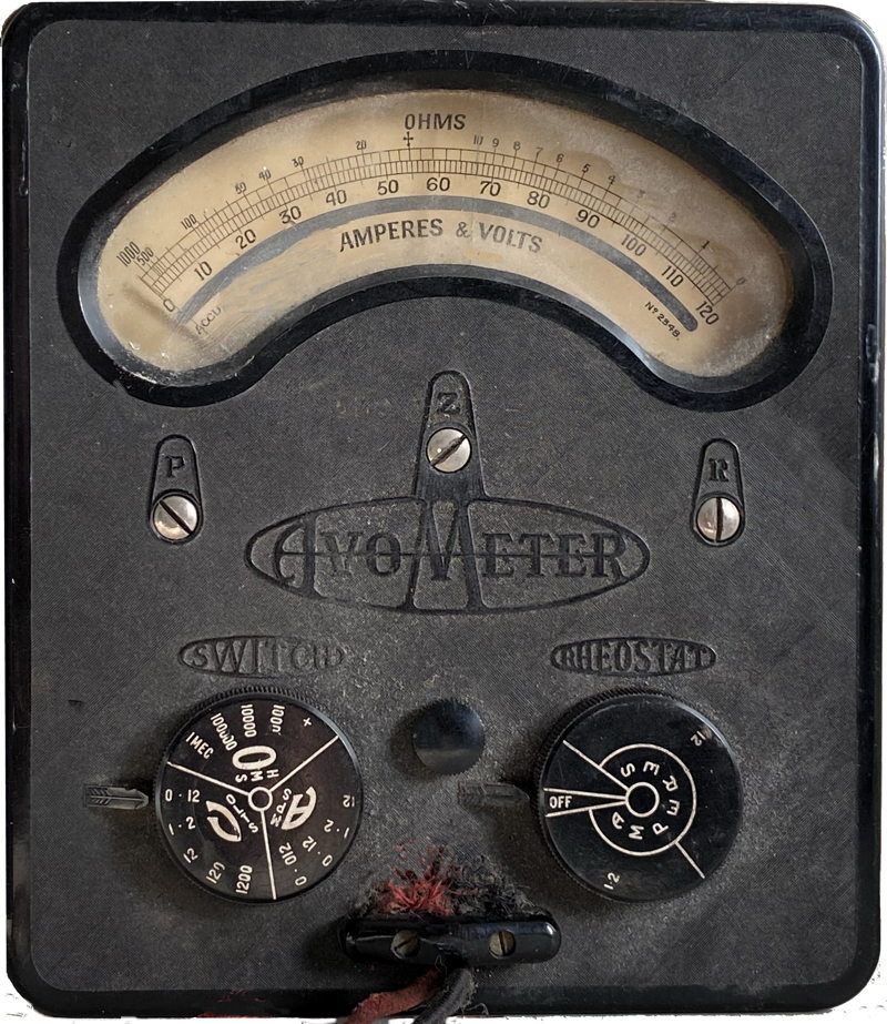
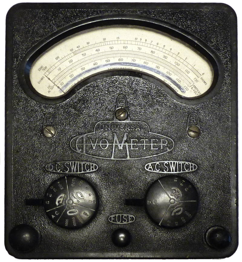
Oiriginal
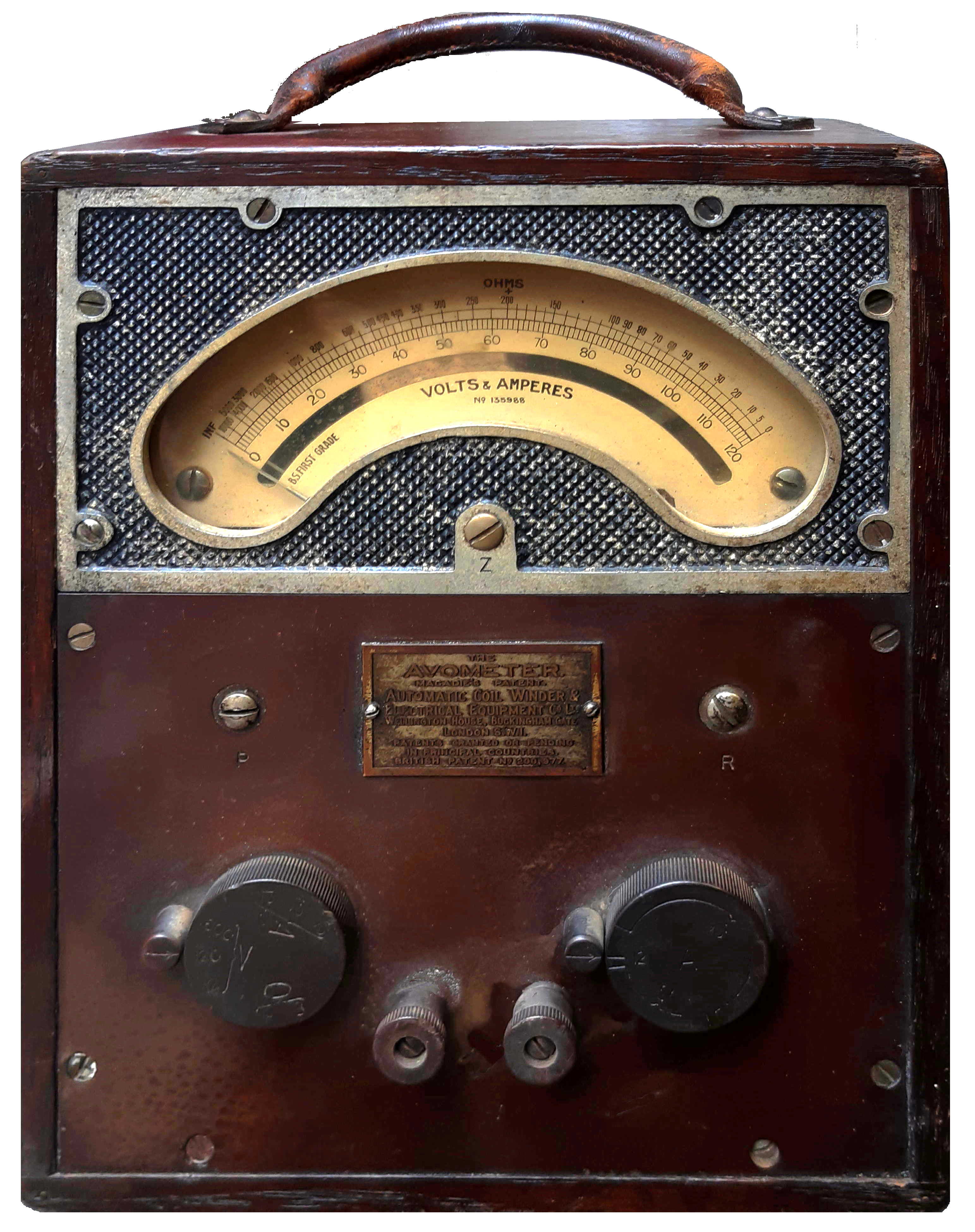
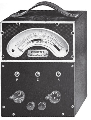
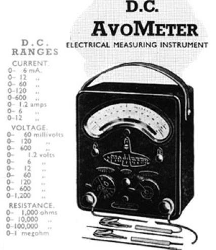
Avometer (Model
1)
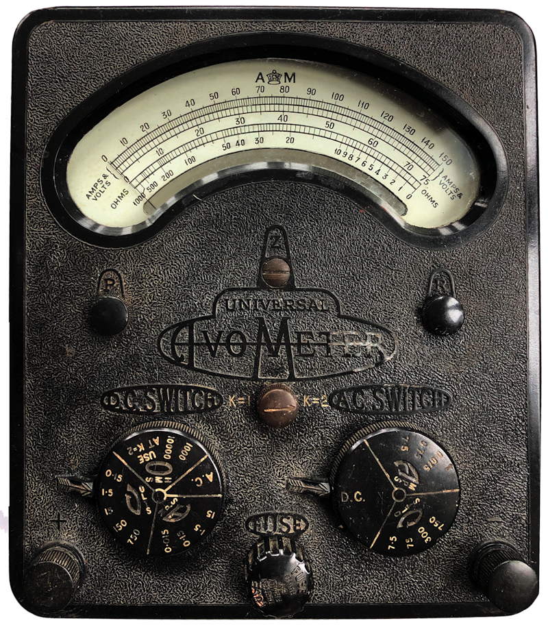
introduced 1923
The meter shown here belongs to the great grandson of Donald
McAdie who gave it to his son in 1943. A letter addressed Dear Bill
indicates that “As the Auto Coil Wiring Coy had presented me with a
model 40 which has over 40 ranges and gives alternating as well as
direct current tests I am sending the old original one to you as you
may find it useful if you have any testing to do. It is in perfect
working order …..”
|
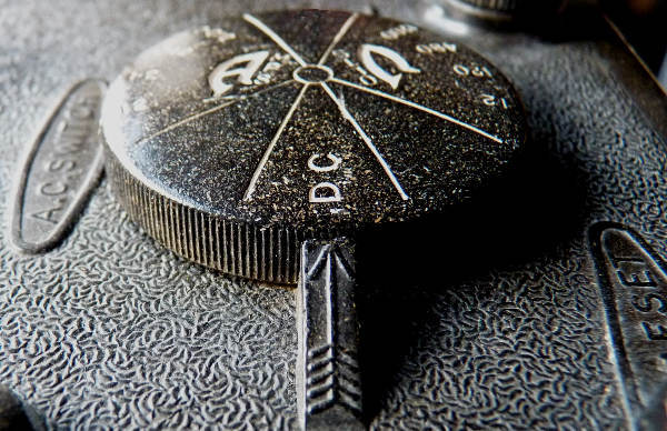
DC 12, 120, 600 volts - sensitivity 12 mA
DC 120 mA, 1.2, 12 A
R 10k ohm (225 ohm center)
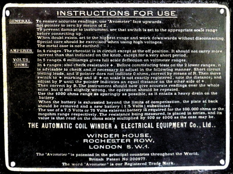
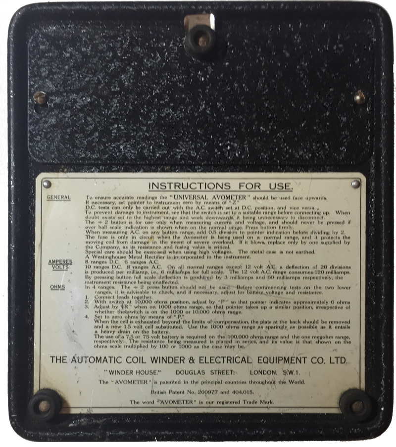
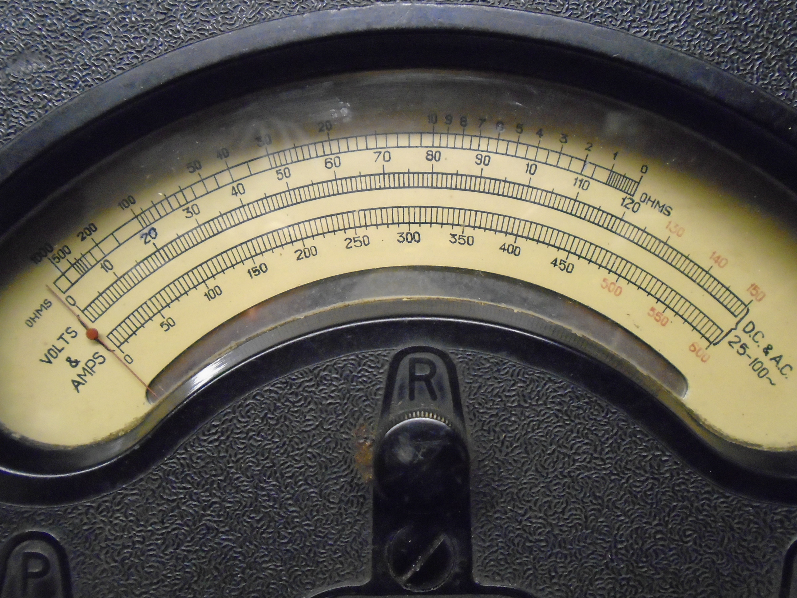
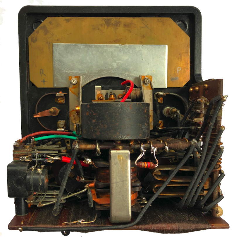
The P and R adjusters are used to compensate for the Potential
(voltage) and the internal Resistance of the internal cells used on the
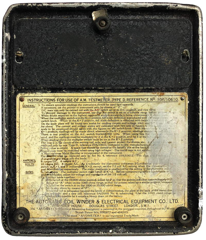
resistance measurement ranges. Instructions here
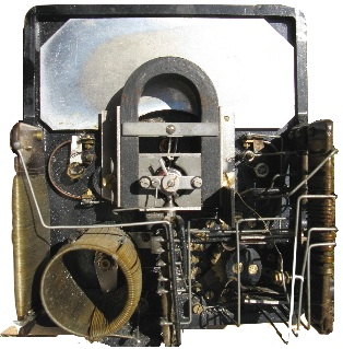
It has been suggested that the movements may have been supplied by
Elliott Brothers. (I have two Elliott meters which can be seen here and here
|
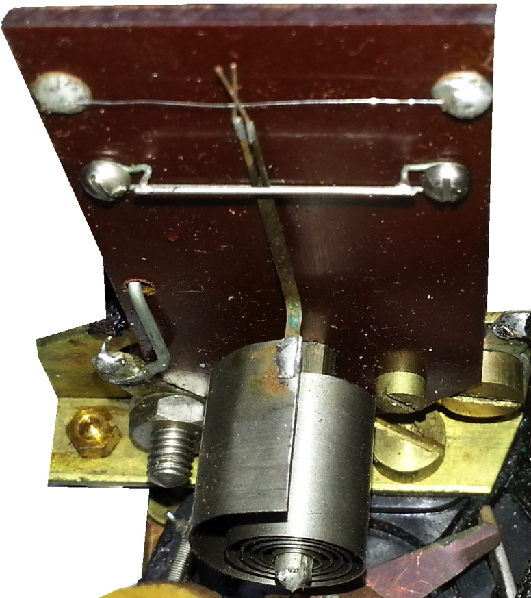
This is one of the images from the patent
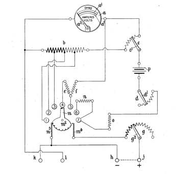
application made by
Donald Macadie in 1923. The basic design incorporating a universal
shunt, internal battery and calibrated scale plate for resistance
measurement has been incorporated in all subsequent models.
The rights to the brand name AVO are held by
Megger today. The American patent (US1593024) can be seen Here
|
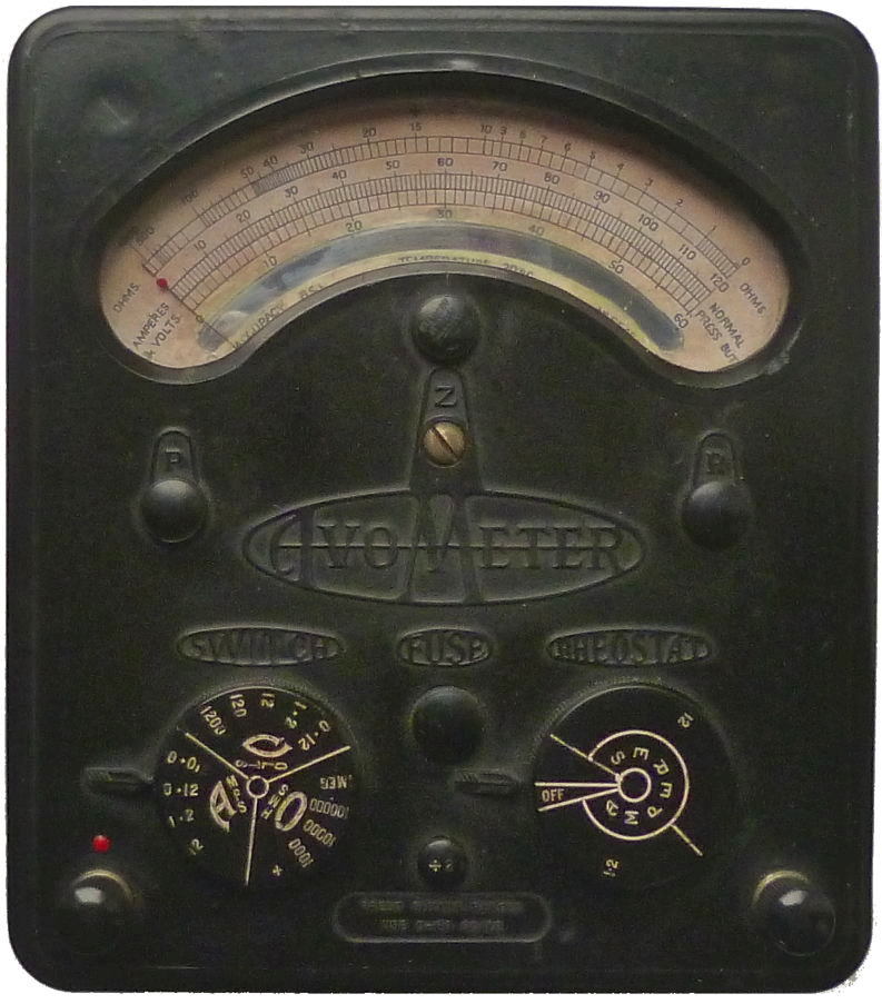
DC Avometer
'13-range'
(Model 2)
Introduced 1927.
|
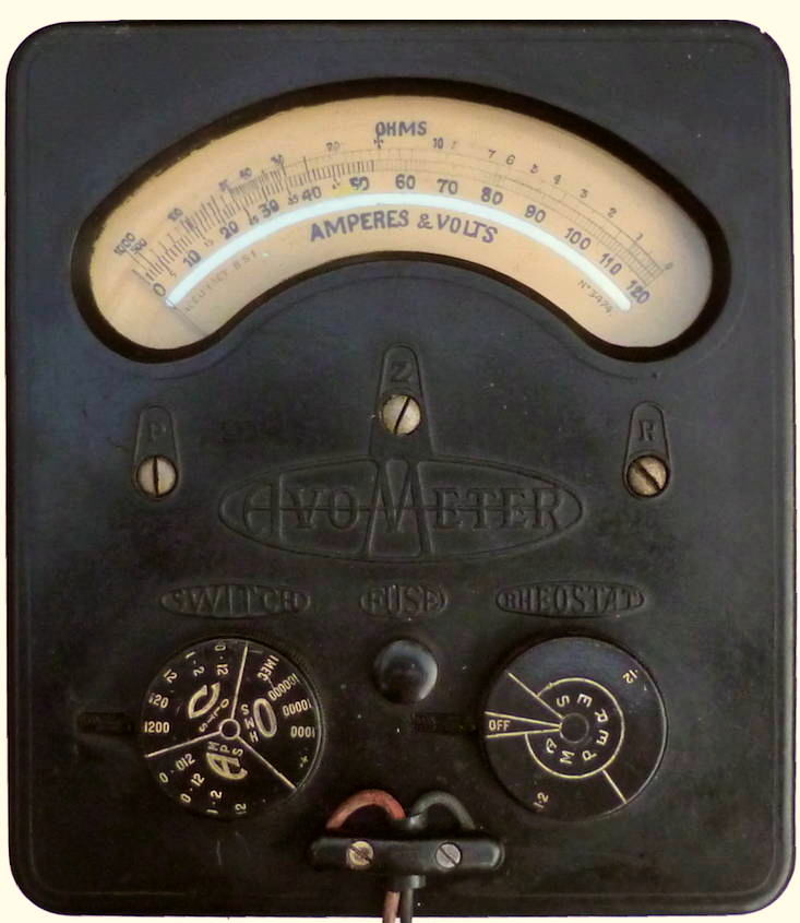
An internal fuse is wired in series with meter.
DC 0.12, 1.2, 12, 120, 1200 volts -
sensitivity 6 mA
DC 12, 120 mA, 1.2, 12 A
R 1k, 10k ohm (12.5, 125 ohm
center)
100k,
1M ohm (1.25, 12.5k ohm center) with external power
(In fact = 7.5, 75 volt ranges,
with no adjustment)
The front panel now manufactured from a one piece Bakelite
moulding and the casing made of aluminium.
Early models such as this were made in the factory at
Rochester Row London SW1
|
|
DC Avometer
'13-range'
(Model 2)
|
This is an example of an intermediate model, it has the same
front
panel as the original 13 range model shown above but is fitted with a
replaceable screw
in fuse on the front panel.
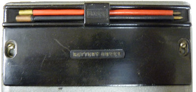
|
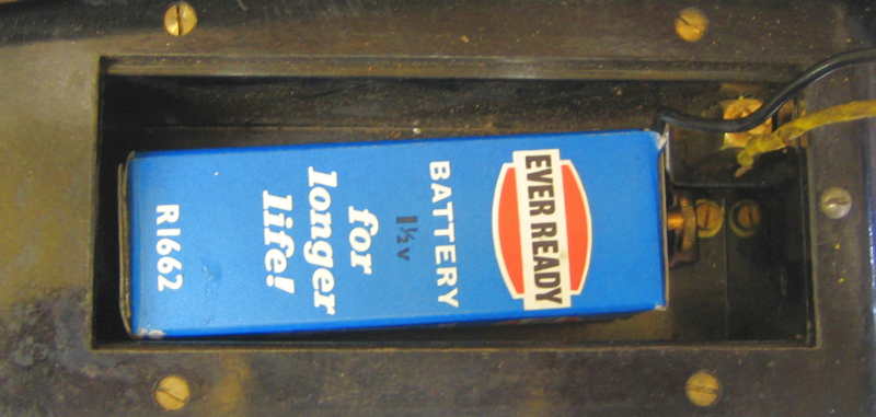
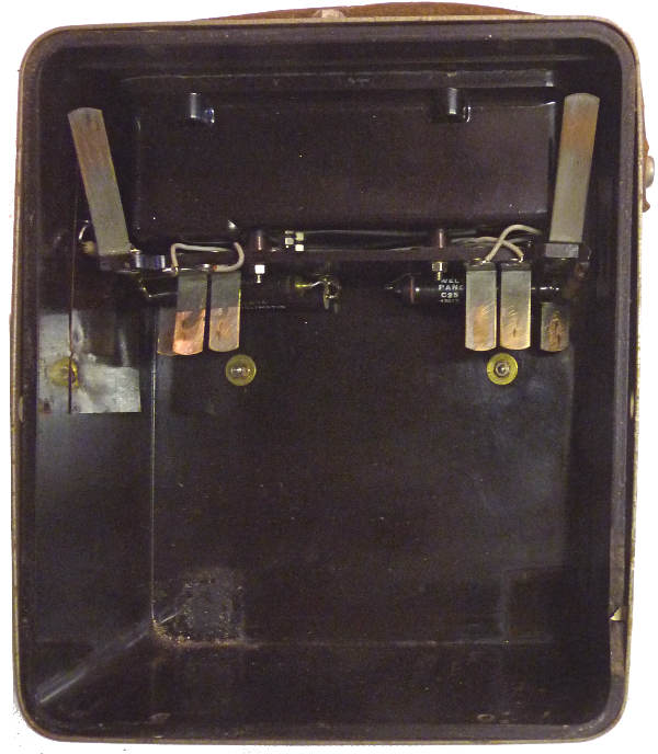
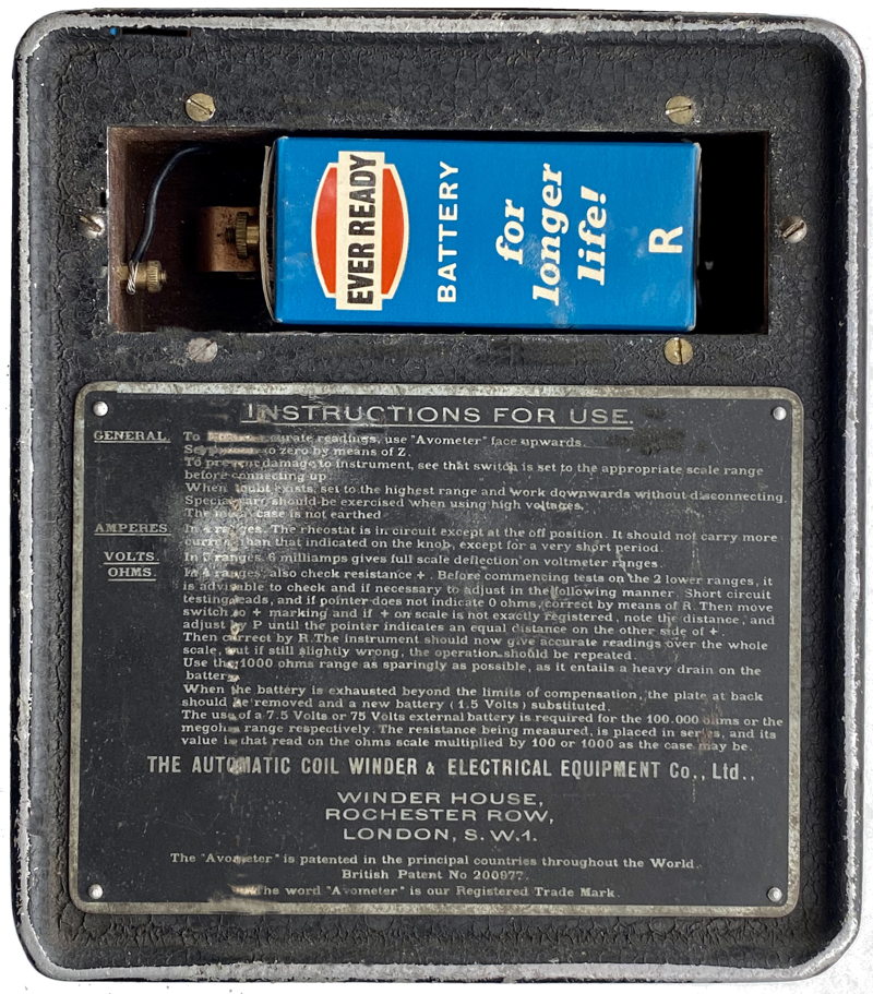
This rear view shows the battery compartment introduced with
the model 2 and used for all models up to the model 7. the battery
shown here is smaller than the Siemens type T or
equivalent for which it was designed.
|
DC Avometer
'13-range'
(Model 2)
This one described here may have been
made in 1934
|
This one is a later version which has a smooth front panel and
has a replaceable screw in fuse on the front panel. A later model
6 introduced around 1934/5 has a divide by 2
button effectively doubling the number of ranges. and has terminals for
the
test leads.
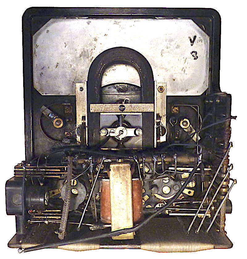
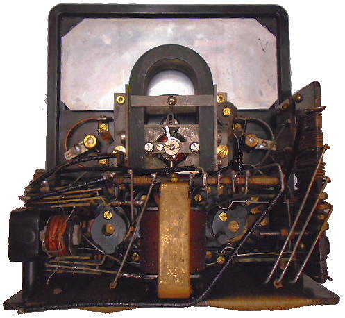
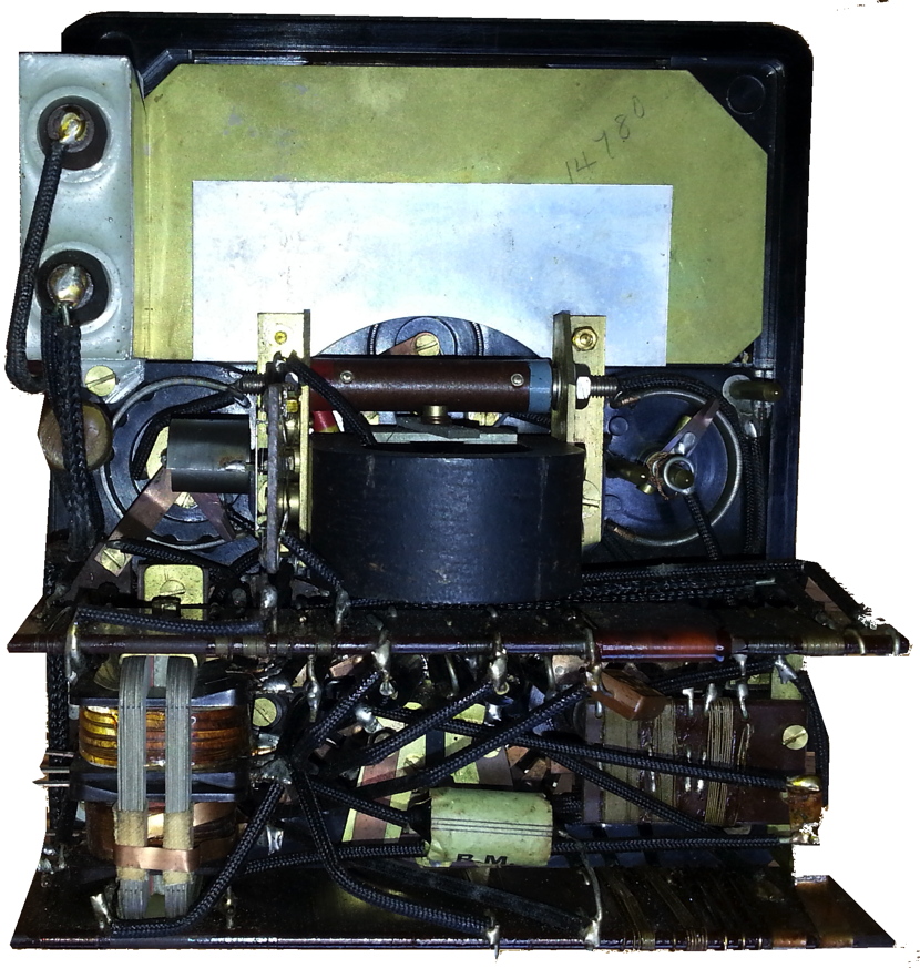
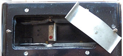
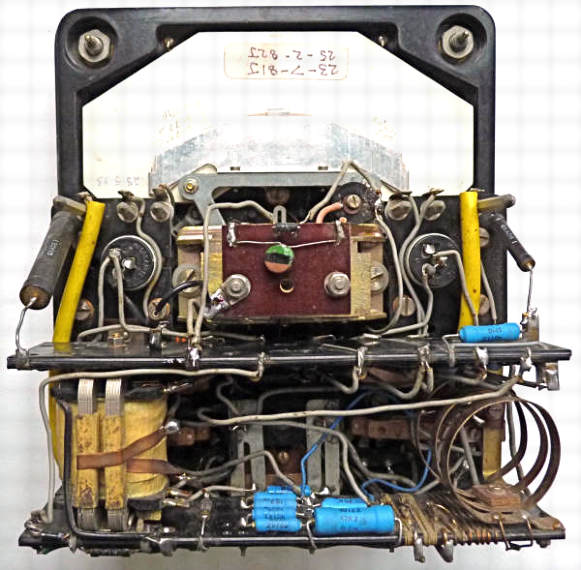
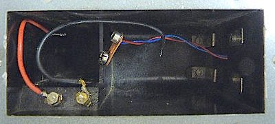
Interior, note that the horse shoe magnet is
aligned with the front panel. In the model 6 and later models using
horse shoe magnets the magnet is
at right angles to the panel (see images below)
|
The meter used an inbuilt 1.5 volt rectangular cell for the
two lower resistance ranges (Siemens type T or
equivalent). This was accommodated in a wooden recess on the underside
of the instrument (as shown above)
Later model 6 with divide by two button (click on image)
|
|
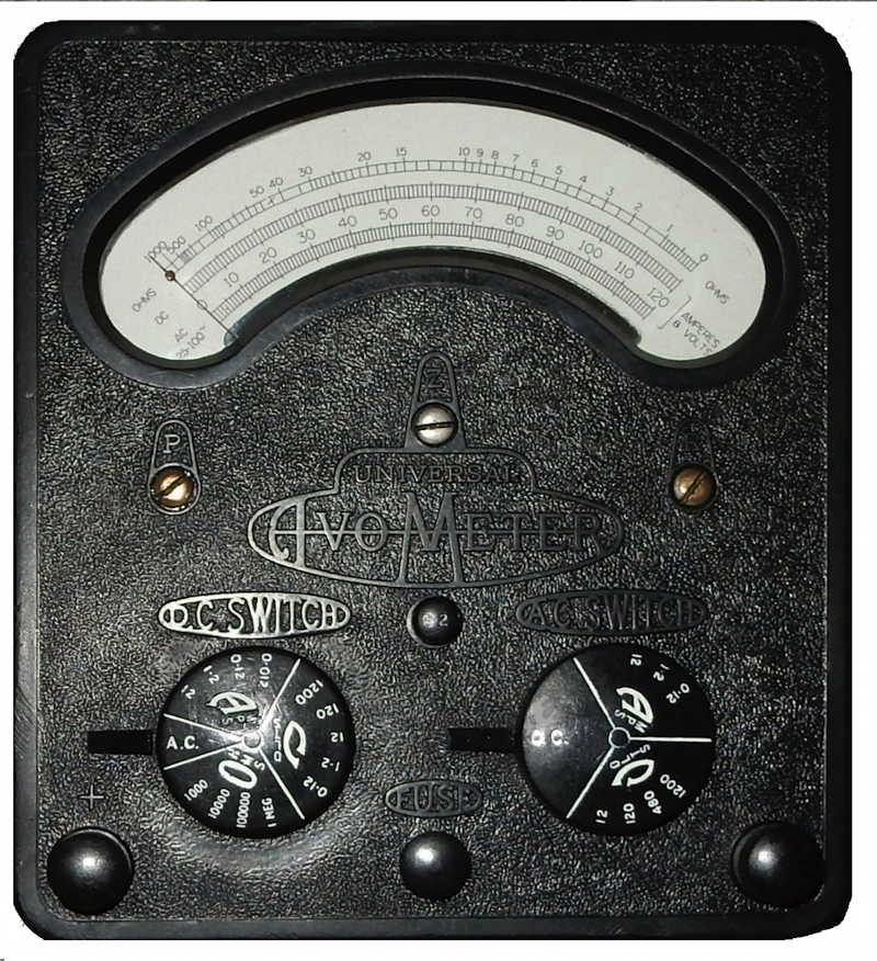
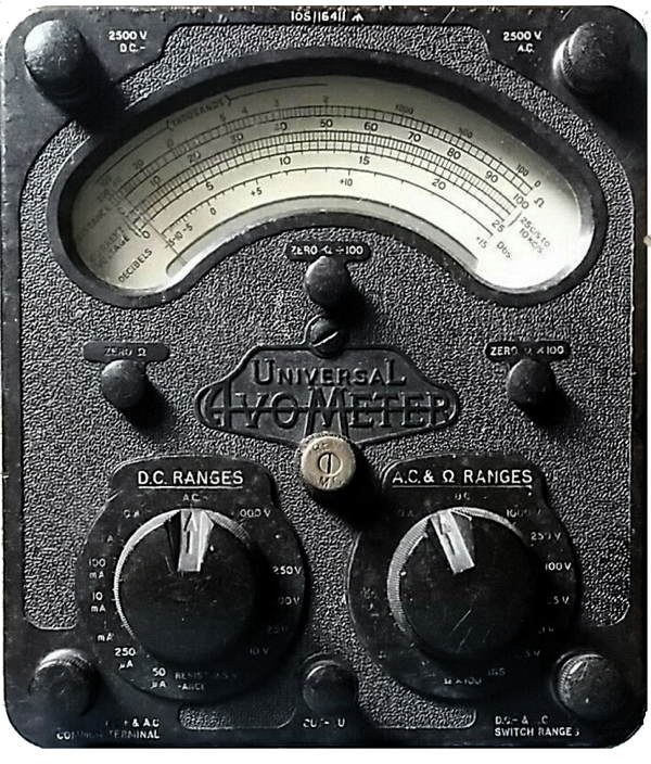
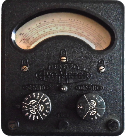
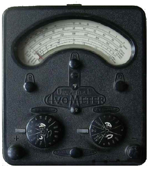
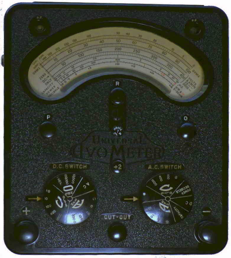
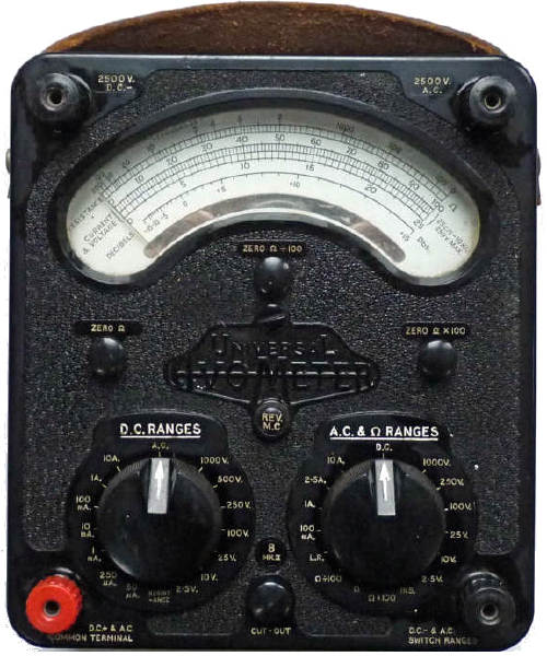
Universal
Avometer
'20-range'
(Model 3)
introduced 1932. This one described here
was made in November 1932
|
Added AC capability using transformer and
copper oxide meter rectifier rectifier.
DC 0.12, 1.2, 12, 120,
1200 volts - sensitivity 6 mA
DC 12, 120 mA, 1.2, 12 A
AC 1.2, 12, 120, 1200 volts
sensitivity: 6 mA on 120, 1200 volts, 120 mA on 1.2, 12
volts
AC 120 mA, 1.2, 12 A
R 1k, 10k ohm
(12.5, 125 ohm center)
100k, 1 M ohm (1.25, 12.5k ohm
center) with external power
(In fact = 7.5, 75 volt
ranges, with no adjustment)
|
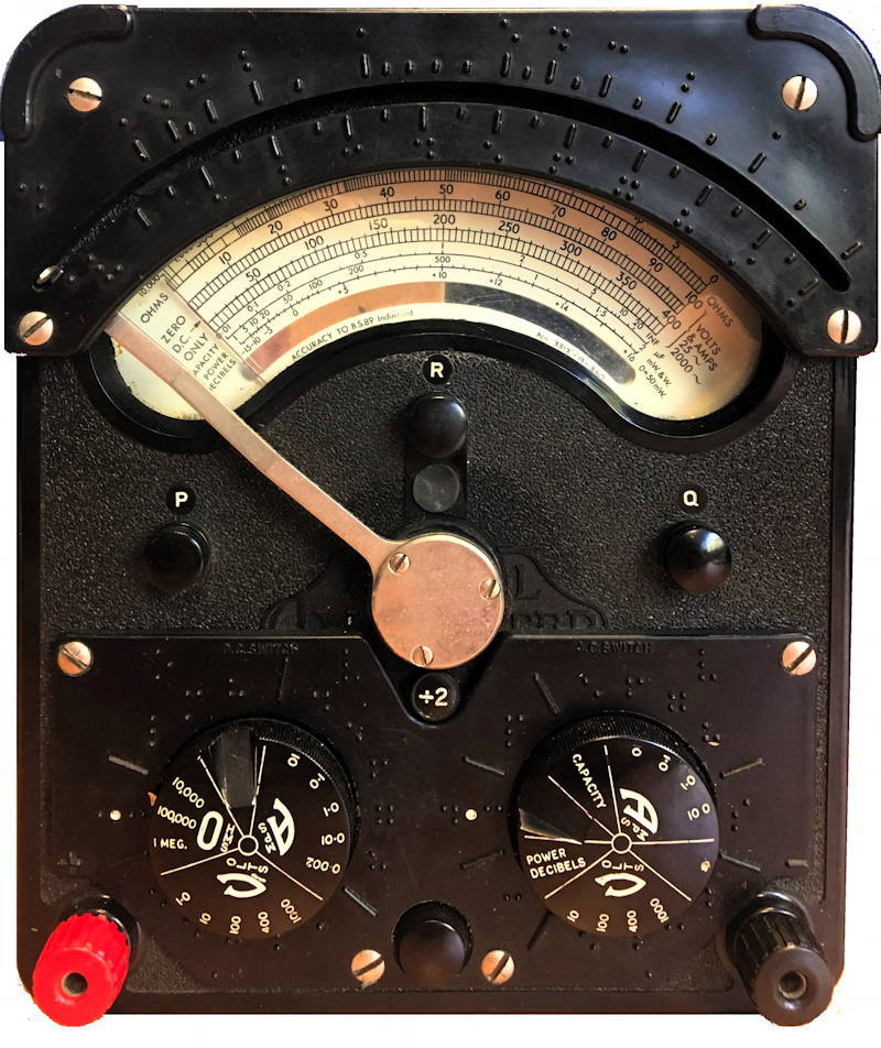
|
|
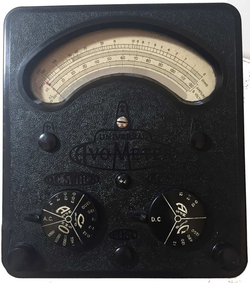
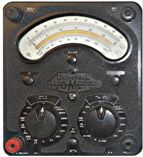
Universal Avometer
'34-range'
(Model 4)
Introduced 1933
A 1934 trade manual advertised this model at
12 guineas (£12.60)
The 13 range DC only model was also available at the time
|
Added 'divide by 2' button - sensitivity
doubled when pressed. Deleted 1.2 V AC range
(probably was inaccurate)
DC 0.12, 1.2, 12, 120, 1200
volts - sensitivity 6/3 mA
DC 12, 120 mA, 1.2, 12 A
AC 12, 120, 1200 volts
sensitivity: 6/3 mA on 120, 1200 volts, 120/60 mA on 12 volts
AC 120 mA, 1.2, 12 A
R 1k, 10 k ohm (12.5, 125 ohm center)
100k, 1M ohm (1.25, 12.5k
ohm
center) with external
power
(In fact = 7.5, 75 volt ranges,
with no adjustment)
(images from Dave Philpott)
|
The meter used an inbuilt 1.5 volt rectangular cell for the
two lower resistance ranges (Siemens type T or
equivalent). This was accommodated in a wooden recess on the underside
of the instrument. An external voltage was needed for the higher
ranges.
|
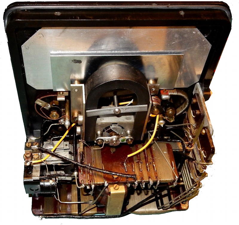
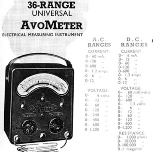
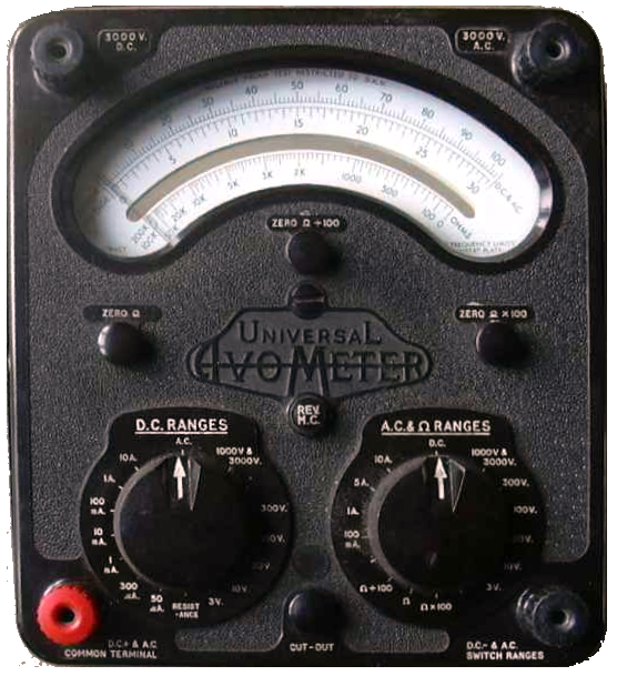
Universal Avometer
'36-range'
(Model 5)
introduced 1934.
|
Added 480 V AC range (240 V when button
pressed)
DC 0.12, 1.2, 12, 120, 1200 volts
- sensitivity 6/3 mA
DC 12, 120 mA, 1.2, 12 A
AC 12, 120, 480, 1200 volts
sensitivity: 6/3 mA on 120+ volts, 120/60 mA on 12 volts
AC 120 mA, 1.2, 12 A
R 1k, 10k ohm
(12.5, 125 ohm center) with 1.5 volt cell
100k, 1M ohm (1.25, 12.5k ohm center) with external
power
(In fact = 7.5, 75 volt ranges, with no adjustment)
|
|
Universal Avometer
'36-range'
(Model 5)
This one descbed here
was made in 1938
|
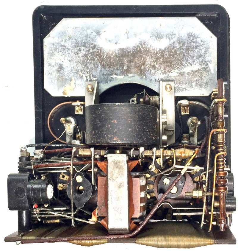
Note the changed orientation of the meter magnet
|
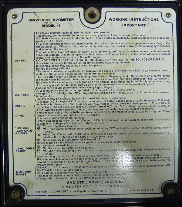
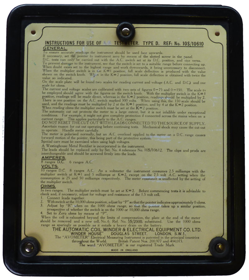
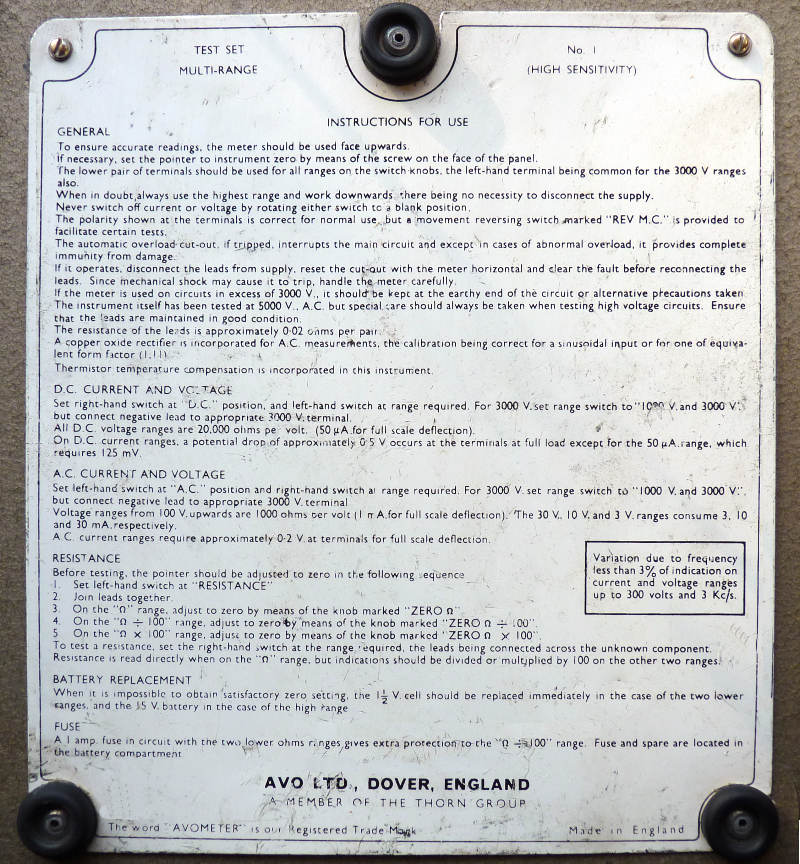
Note changed instruction plate
|
|
DC Avometer
'22-range'
(Model 6)
Introduced about 1934/5. This one described
here may have been made in 1936
|
Added 'external battery adjust' (Q
knob on Models 7) not incorporated into Universal
DC 0.12, 1.2, 12, 120, 1200 volts - sensitivity 6/3
mA
DC 12, 120 mA, 1.2, 12 A
R 1k, 10k ohm (12.5, 125 ohm
center)
100k, 1M ohm
(1.25, 12.5k ohm center) with external
power.
This image is from an AVO 1935
catalogue when it was
priced at 8 guineas (£8.40)
|
|
|
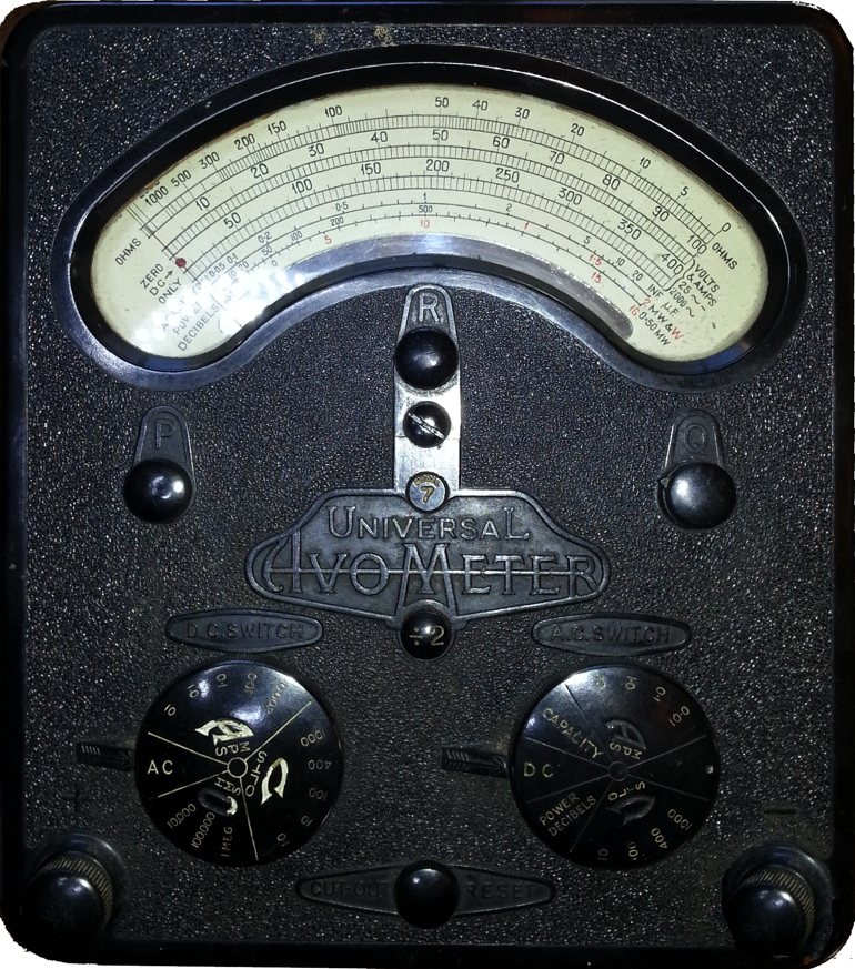 
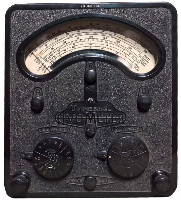
Universal Avometer
'46-range'
Model 7 (early)
Introduced 1936. The first one shown here was made in 1944 and
the second in 1945.
Note the differences in the front panel mouldings. The second includes
"MODEL 7
UNIVERSAL" in a sans serif font rather than the more usual
"UNIVERSAL"
Note also that the zero adjuster on the earlier model is made
of brass and the later ones are black Bakelite. This seems to be true
for all instruments made after 1944 or thereabouts.
Versions of this
meter were made for the British Army and labelled with
the part number ZD00021.
those for the Air Ministry were known as Testmeter Type F with leads
labelled with the stores reference 10S/1
or 5QP/1
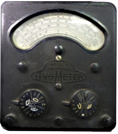
Universal Avometer
'46-range'
Model 7 (later)
Introduced 1936,this one described
here was made in 1948 but this model was still being
produced at the end of 1951
|
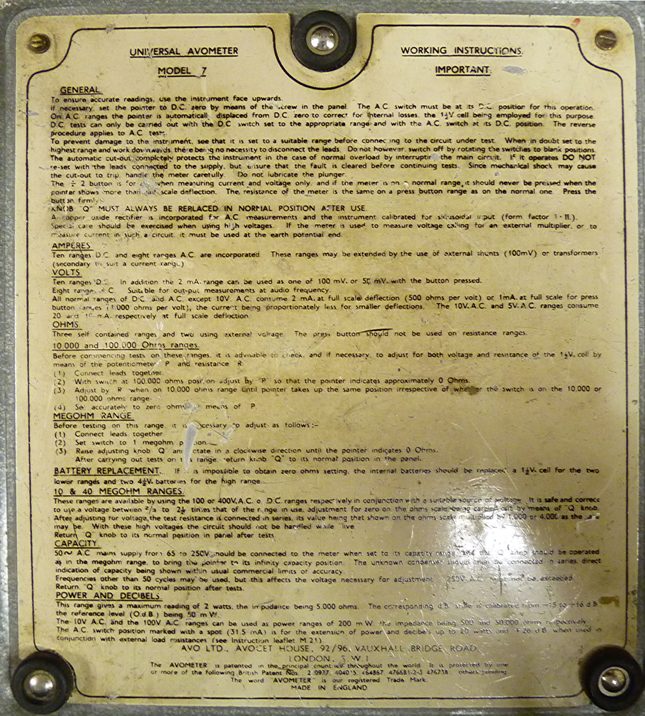
The Model 7 was the first with with auto cut out instead of a fuse and
decimal scale (rather than duodecimal as in previous models) and has
the
basic design on which the model 40 and model
8 were based. It has higher sensitivity and was the first with dB scale
and block magnet assembly for the meter movement. Earlier models would
have horseshoe magnet on the meter (see the model 40 below)
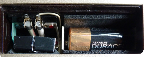
Bakelite or aluminium case with battery cover designed to hold
the test prods.
DC
1, 10, 100, 400, 1000 volts - sensitivity 2/1 mA
DC
2, 10, 100 mA, 1, 10 A
AC
10, 100, 400, 1000 volts
sensitivity: 2/1 mA on 100+ volts, 20/10 mA on 10 volt
AC
10, 100 mA, 1, 10 A
R
1k, 10k, 100k, 1 M ohm (50, 500, 5k ohm center) Q knob
required on highest range
C
0.01 - 20 uF (1 uF center)
Power
2 W into
5k ohms (100 volts)
[Earliest models had 4 W into 4k ohms (127 volts)] Click here for
Instructions
 1944 1944
1944
Early models have horse shoe magnets and bimetallic
temperature compensation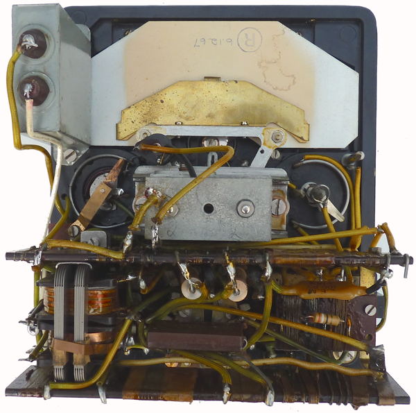 1948 1948
1948
After 1948 (or late 1947)
Alnico block
magnets used for the meter rather than the horse shoe of the earlier
instruments. It seems that meterers with Alnico magnets have an A in
the serial number.
AVO used a standard movement
design for most products, but with small variations. This were referred
to as the Movement 45 (1949/1950), which was superseded by Movement 46
(1965).
|
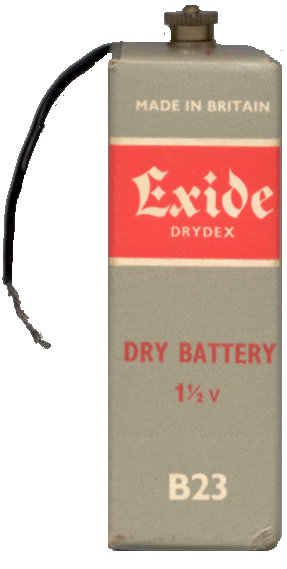
Internal 9V battery 2x4.5V Siemens type P3 (cycle lamp type)
for high
resistance range and as previously a 1.5 volt cell Siemens type T or
equivalent for lower ranges. Other equivalents are Exide B23 and Ever
Ready R1662 which have these dimensions:
1.125 x 3.3125 x 1.125 inch /
29 x 84 x29mm
 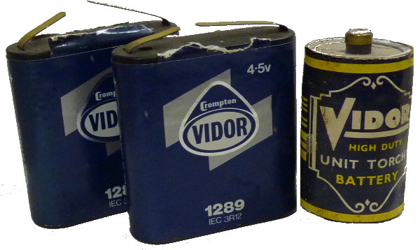
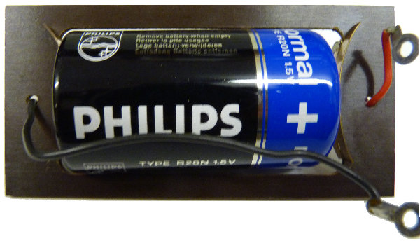
The
rectangular battery became obsolete many years ago and most
owners resorted to soldering a U2 or equivalent cell in its place.
(click on image)
AVO manufactured a simple device
with two contacts and two leads to
enable a U2 or D size cell
to be
used in their model 7 and model 40 meters. The 4.5 volt batteries are
currently available but the simple modification shown here enables a
readily available PP3 9Volt battery to be used.
You can use an adapter which uses 3 AA cells as shown below,
but beware that they are a very tight fit for the battery compartment
and you will need to perform a little surgery to reduce
the depth. I removed the labels and used a Dremmel tool to grind
away a millimetre or two from the top and bottom edges visible here.
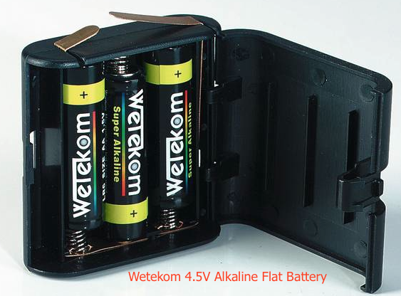
these are available from westfalia.net
|
Military Universal Avometer
Model 7 (ZD 00021)
|
This is a standard model 7 instrument supplied for the British
army dating from 1951
|
|
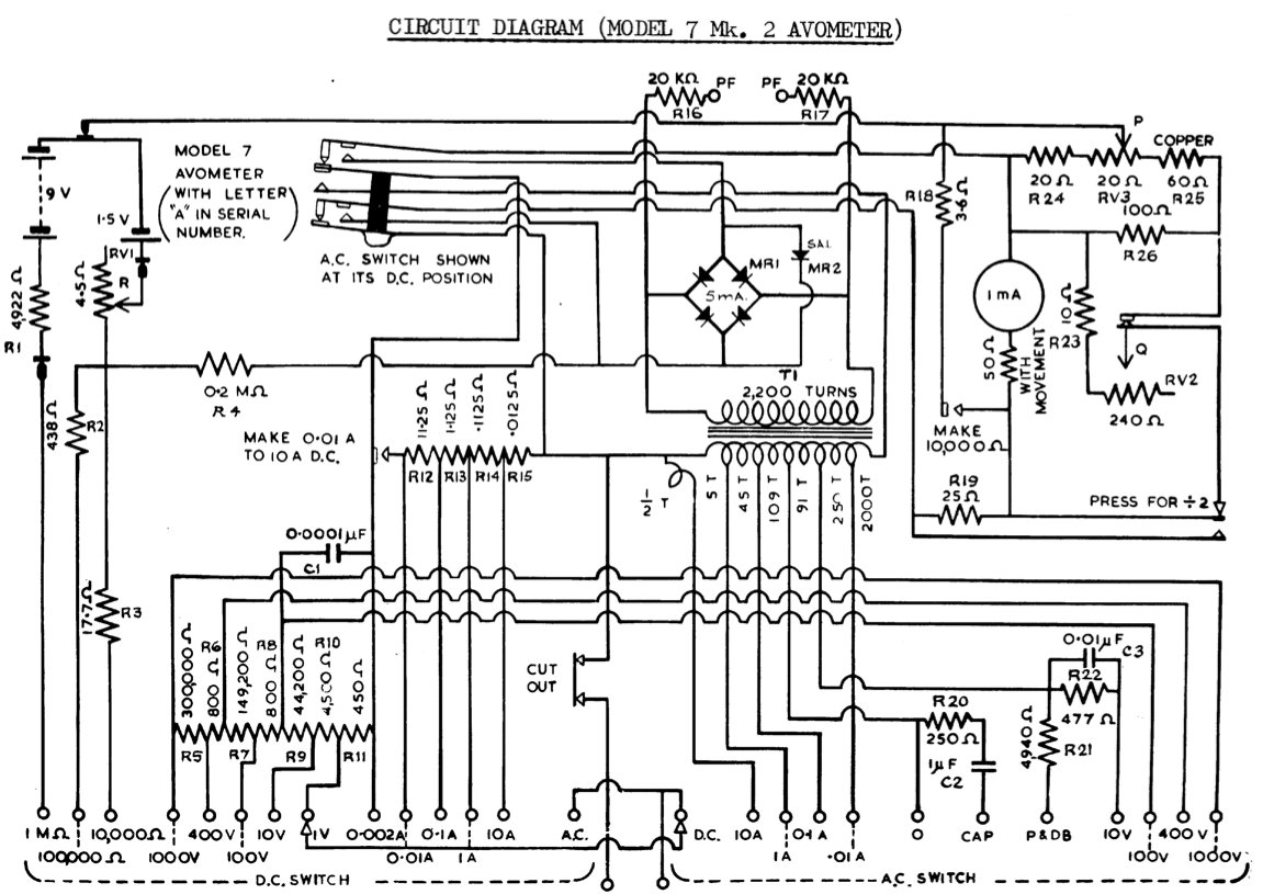
Universal Avometer
Model 7 Mark II
Introduced about 1952 and last manufactured
1986.
This one described here was
made in 1955
|
New movement design but no external changes initially. At some
point during the 1950's, added power factor
jacks for P.F.
unit and red and black banana terminals in 1956. Last manufactured
1986.
Model 7 Universal AvoMeter MKII (from 1960 advert)
A multi-range A.C./D.C. Measuring Instrument providing 50
ranges of readings on a 5-in. hand-calibrated scale fitted with
anti parallax mirror.
Range selection is effected by means of two rotary, switches,
which are electrically interlocked. Full scale deflection on voltage
ranges is obtained with a consumption of I mA or 2 mA according to
whether the -:- 2 press button is used or not. The total resistance of
the meter is 500,000 ohms.
The instrument is self-contained, compact and portable, simple
to operate and almost impossible to damage electrically. It is
protected by an automatic cut-out against damage through severe
overload.
CURRENT: A.C. and D.C. 0 to 10 amps.
VOLTAGE: A.C. and D:C. 0 to 1,000 volts.
RESISTANCE: Up to 40 megohms.
AUDIO-FREQUENCY POWER: 0-2 watts.
CAPACITY: 0.01 to 20 mFds.
DECIBELS: -25dB to + 16dB.
POWER FACTOR AND POWER can be measured in A.C. circuits
by means of an external accessory (the Universal AvoMeter Power Factor
and Wattage Unit). Two models of this Unit are available, one for use
with the Model 7 Avo Meter and the other with the Model 40 AvoMeter,
but in either case the Avo Meter must be a model fitted with sockets
marked "P.F." for connection to the Unit. All recently produced Avo
Meters have been fitted with these sockets.
|
(click on image)
|
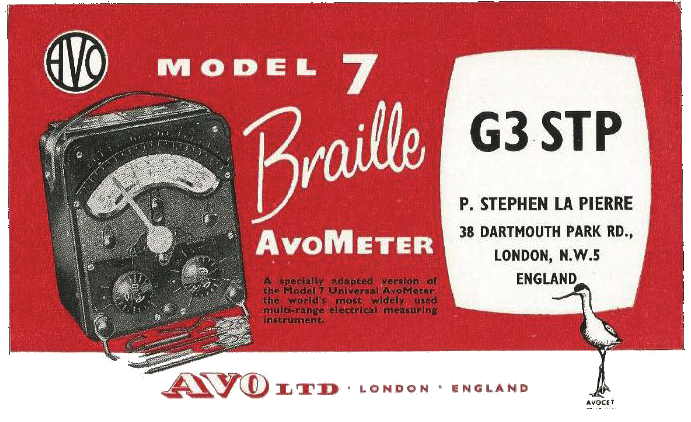
Universal Avometer
Braille Model 7 Mark II
|
Introduced in 1951, the Braille model 7 meter was modified for
use by visually-impaired servicemen and consisted of a more-or-less
standard meter with a
'feeler mechanism' pointer over the scale, swung from the movement. You
will note that the Braille range markers are on the front face of
the meter rather than on the knobs. There are Braille markings moulded
above the arc of the scale window for each of the ranges. The switch
positions have similarly-marked Braille mouldings and a
milled groove on each of the range selector switches so that the
positions
can be found by touch.
This idea was also implemented on the Model 8 which was
introduced in 1951 though the model 7 and 40 meters continued to have
engraved knobs until the end of production.
The markings on the braille scale are said to allow users to interpret
readings to within 1% of FSD.
See picture below of a Braille model 8 Mk3
|
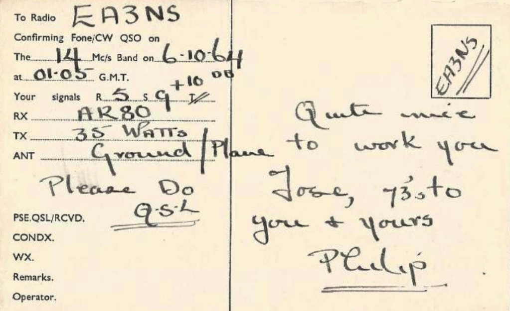
This Radio Ham QSL card suggests
that AVO may have rovided operators with these cards as a way of
advertising their products. (images from Aitor de Elejabeitia)
|
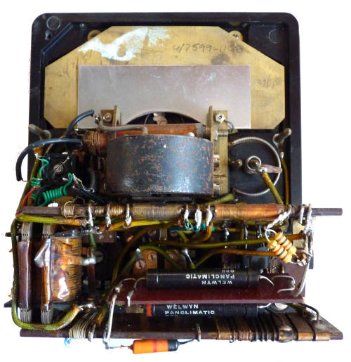
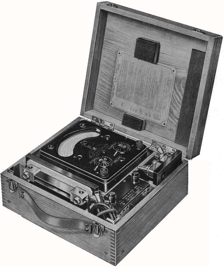
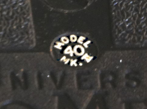
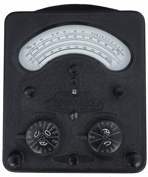
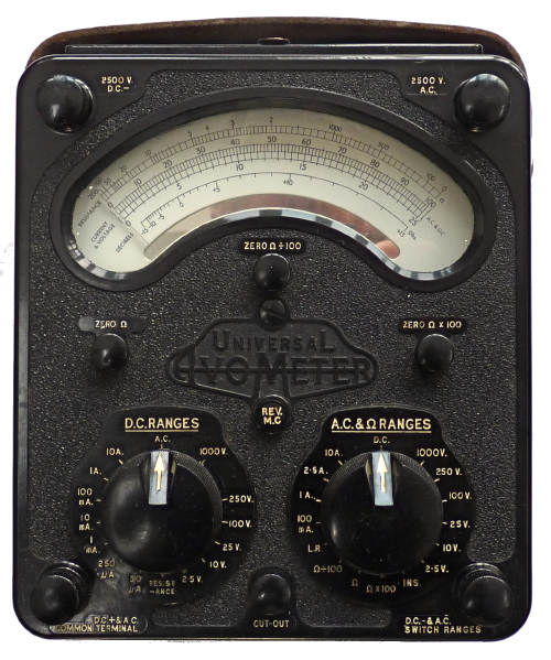
Universal Avometer
Model 40
Introduced 1939. This one described
here was made in
1946
|
Universal Avometer model 40 re-done after Model 7: same as
Model 7
except ranges and sensitivity. No dB scale. Until about 1948 meters
would
have had a
horseshoe magnet such as this one. Several components including the
rectifier have been replaced in this instrument. The scaling is similar
to that on the model 5 Pre-War 36 range instrument which included a
480
volt AC voltage range, more suitable for power engineers who would
want the facility to measure 3 phase mains voltages.
DC 0.12, 1.2,
12, 120, 480, 1200 volts - sensitivity 6/3 mA
DC
12, 120 mA, 1.2, 12 A
AC
12, 120, 480, 1200 volts
sensitivity: 6/3 mA on 120+ volts, 60/30 mA on 12 volts
AC
12, 120 mA, 1.2, 12 A
R
1k, 10k, 100k ohm (20, 200, 2k ohm center)
Q knob required on highest range
Housed in aluminium case.
|
|
Special version of Model 40 (7.5mA FSD)
made in 1947
|
The scale plate is compressed (or expanded!?) to 150/600 from
the normal 120/480. The ohms range is truncated to suit, thus does not
extend to FSD.
Red paint is used to demarcate the 25% over-read allowed for on this
meter, and there is also an error- '100' is painted in as '10'.
The range knobs are standard for a Model 40, all the way up to
120v,480v, and 1,200v.
It has no significant advantages over a Model D, although arguably a
bit more flexibility on resistance, with 12, 120, and also 1,200 ohms
at centre scale with the 9 volt internal source.
It assumed that this was part of a small batch for a particular
customer.
|
This unusual meter belongs to Dave
Philpott who has sbmitted this picture (open the image in
a new window to view more closely)
|
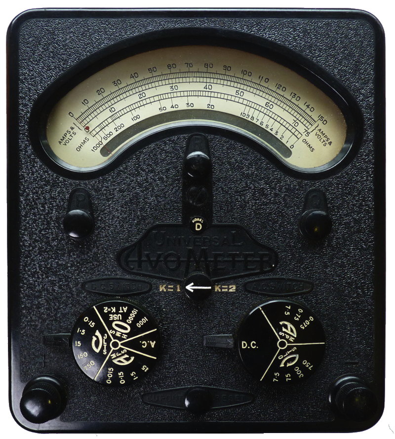
Universal Avometer Model D
AM Testmeter Type D with
leads. 10S/10610
Type D connecting leads NO.4 10S/10612
Type D Battery 5]/2000
Type 15 Fuse Testmeter, type D 10s/10611 (for early models only)
|
This is an early (1939)
version of the one shown below, the construction including a fuse
is similar to that of the 36 range model 5
|
|
Universal Avometer Model D
(AM part number 10S/10610)
1940-47 This one described here
was made in 1945
|
Military version (Air Ministry). Modified Model 40; Switch
instead of 'divide by 2' button. No Q potentiometer and only two
resistance ranges.
DC 0.3, 3, 30,
300, 1500 volts - sensitivity 5/2.5 mA
DC
30, 300 mA, 3, 30
AC
15, 150, 600, 1500 volts
sensitivity: 5/2.5 mA on 150+ volts, 50/25 mA on 15 volts
AC
15, 150 mA, 1.5, 15 A
R
1k, 10 k ohm (25, 250 ohm center)
|
This meter only requires a single 1.5 Volt cell unlike the
model 7 detailed above.
The
rectangular battery became obsolete many years ago and most
owners resorted to soldering a U2 or equivalent cell in its place.
|
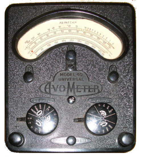
Universal Avometer Admiralty
Pattern Model 47A.
Note that on this model 40 the front panel moulding includes
"MODEL 40 UNIVERSAL" rather than the more usual "UNIVERSAL"
and that a sans serif font has been used.
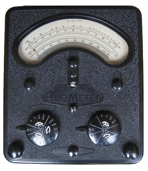
Universal Avometer Admiralty
Pattern Model 48A.
|
The model
47A is a Military version (Admiralty) modified version of the model 40
DC 0.12, 1.2,
12, 120, 480, 1200 volts - sensitivity 6/3 mA
DC
12, 120 mA, 1.2, 12 A
AC
12, 120, 480, 1200 volts
sensitivity: 6/3 mA on 120+ volts, 60/30 mA on 12 volts
AC
12, 120 mA, 1.2, 12 A
R
1k, 10k, 100k ohm (20, 200, 2k ohm center)
Q knob required on highest range
The Model
48A is a Military version (Admiralty) of the
AVO Industrial Test Set
incorporating a modified Model 40 multimeter.
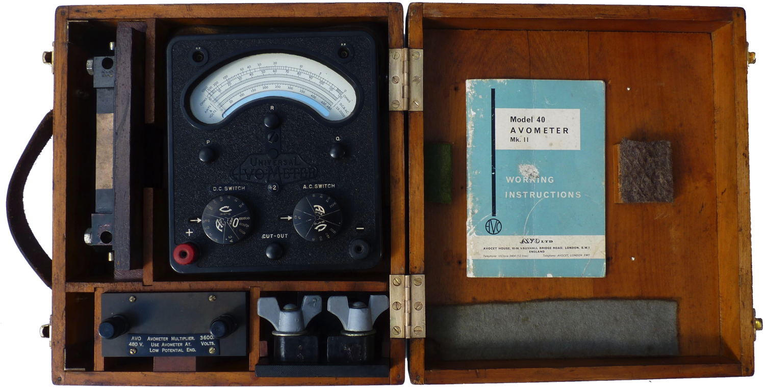
This is an admiralty pattern 48A (described here) made in 1944 but housing
a much later model 40 Mk.II meter
The model 48A is a 47A meter unit
together with additional shunt, transformer and multiplier to enable it
to additionally read:
DC 3600 V
DC 120, 480 A
AC 60,120 A
DC 0.12, 1.2, 12, 120, 480, 1200 V
DC 0.012, 0.12, 1.2, 12 A
AC 12, 120, 480, 1200 V (25-100Hz)
AC 0.012, 0.12, 1.2, 12 A
OHMS: 1k, 10k, 100k
it requires an external 9 - 25V
supply for the 100k ohms range, uses the internal 1.5V rectangular cell
for other ranges (Admiralty part number 14120)
|
 Avo Industrial Test Sets Avo Industrial Test Sets
Model 1.
A test set comprising a Model 40 Avometer with the following
4,800V Multiplier, 120A Shunt, 480A Shunt and 60/240A Transformer.
Model 2.
As an alternative, a test set can be supplied comprising a Model 7
Avometer with the following:
4,000V Multiplier, 100A Shunt, 400A Shunt and 50/200A Transformer.
|
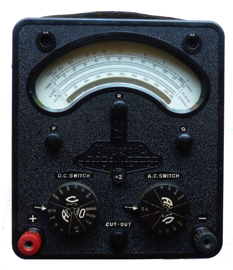
Universal Avometer
Model 40 Mark II
Introduced 1952 This one described
here was made in 1975
In 1980 this instrument would have cost £124.60 exc VAT 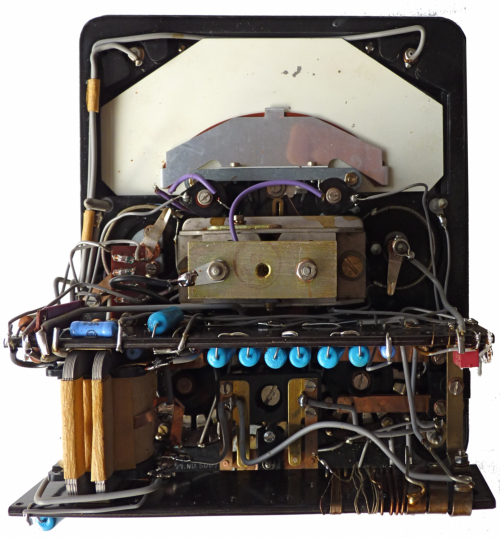
|
New movement design but no external changes initially. At some
point during the early 1950's power factor jacks for
P.F. unit were added and the banana terminals in 1956. This instrument
has a germanium
rectifier, which must have been a later change. Last manufactured 1986.
Housed in aluminium case.
Model 40 UNIVERSAL AVOMETER Mk.II (from 1960 advert)
A self-contained multi-range A.C./D.C. instrument providing 40
ranges of current, voltage and resistance. Higher ranges are obtainable
with the aid of external shunts, transformers or multipliers.
Range selection is accomplished by means of A.C. and D.C. switch
knobs, and in addition a -:- 2 press button halves the value of any
current or voltage range. Full scale deflection on voltage ranges is
obtained with a consumption of 3mA. or 6mA. according to whether the
press button is used or not. Total resistance of the meter is 200,000
ohms.
The instrument is similar in design and appearance to the Model 7
AvoMeter, and is fitted with an automatic overload cut-out.
CURRENT: A.C. and D.C. 0 to 12 amps.
VOLTAGE: A.C. and D.C. 0 to 1,200 volts.
RESISTANCE: Up to I megohm.
POWER FACTOR AND POWER can be measured in A.C. circuits by
means of an external accessory (the Universal AvoMeter Power Factor and
Wattage Unit). Two models of this Unit are available, one for use with
the Model 7 Avo Meter and the other with the Model 40 AvoMeter, but in
either case the Avo Meter must be a model fitted with sockets marked
"P.F." for connection to the Unit. All recently produced Avo Meters
have been fitted with these sockets.
|
Battery compartment with cell carrier (see above) in position.
Front panel mouldings for most models changed in
the late 1940's, the knobs were deeper and the panel markings were
white filled and incised rather than raised as
previously.
The same moulding was often used for
the front panel and the model number and Mk was often but not always indicated as shown
here.
|
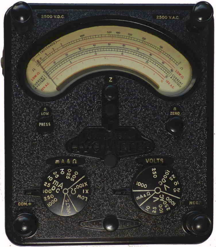
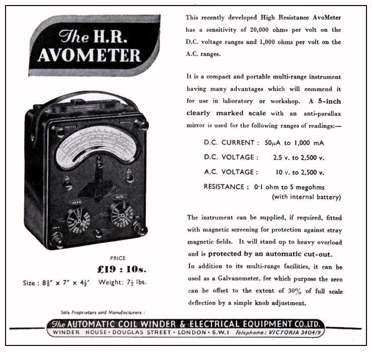
High-Sensitivity HR Avometer
model 1
High-Sensitivity HR Avometer
model 2
Note the diffferent ohms scale and buutton labels.
|
First with 20,000 ohms
per volt; no transformer or AC current ranges on this model.
High-voltage terminals added.
No Q knob or 'divide by 2' button. Permanently attached shunt chain
taking 1/4 of meter current
DC 2.5, 10,
25, 100, 250, 1000, 2500 volts - sensitivity 50 uA
DC
0.05, 0.25, 1, 2.5, 10, 25, 100, 250, 1000 mA
AC
10, 25, 100, 250, 1000, 2500 volts - sensitivity 1 mA
(Non-linear scale for 10 V)
R
resistance 'Low ohms' (about 3.7 ohms center, reversed
some models lacked this)
50k, 5
M ohm (500, 50k ohm center)
 |
This instrument was available in two versions model 1 and
model 2, the latter had an extended resistance range and
could measure up to 20 M ohm. Instruments in screened cases were also
available.
|
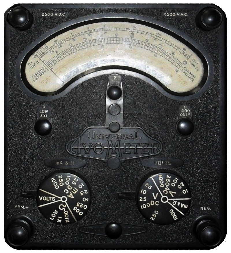
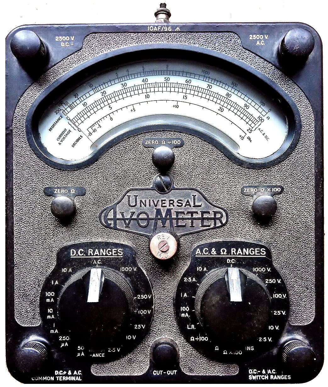
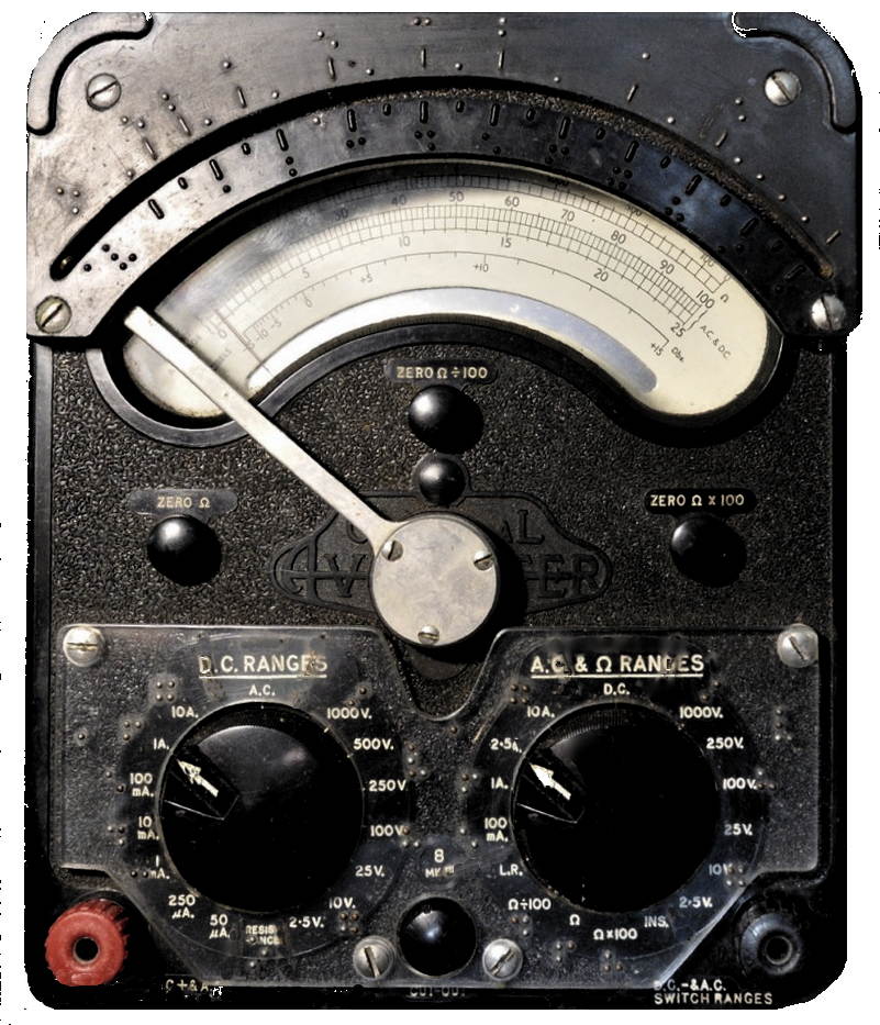
Universal Avometer Model 8
(sometimes called
'Mark I')
Introduced 1951. I don't know when this one described here was made as the movement is a replacement and
undated.
Versions of this meter were made for the British Army and labelled with
the part number ZD00579
|
Development of High-Resistance model, added back transformer
and
normal switch design.
Meter reverse button added. Interior re-design to incorporate
commercially available variable resistors on resistance ranges.
Bakelite case with battery cover designed to hold the test prods.
DC 2.5, 10,
25, 100, 250, 1000, 2500 volts - sensitivity 50 uA
DC
0.05, 0.25, 1, 10, 100 mA, 1, 10 A
AC
2.5, 10, 25, 100, 250, 1000, 2500 volts
sensitivity: 1 mA on 100+
volts, 4 mA on 25, 10 mA on 10, 40 mA
on 2.5
AC
100 mA, 1, 2.5, 10 A
R
2k, 200k, 20 M ohm (20, 2k, 200k ohm center)
Also
LR (=
0.325 volts, for use with low range of Resistance Range Extension unit)
and Ins. (2 M ohm center, with external power)
 open in new window to see full size open in new window to see full size
|
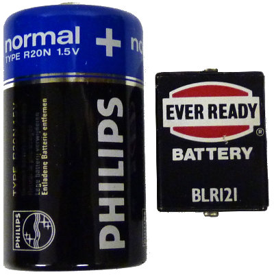
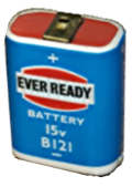
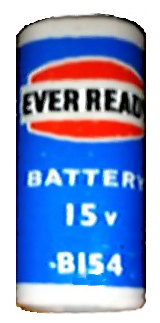
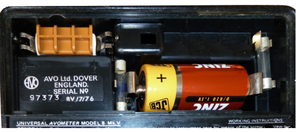
The
model 8 was designed to accommodate the more readily available
cylindrical U2 cell (size D) and because of the higher resistance
ranges a small
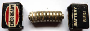
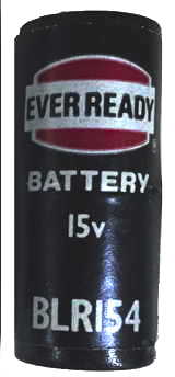
15 Volt battery. Early models of the AVO 8 use the B121. This battery
was superseded by the B154 type (squarer cross section) and in 1970/71
AVO started issuing
instruments with an adapter to accommodate the smaller dimensions.
The B121 and B154 were made with ten biscuit type layer cells. Modern
equivalents are constructed from round button cells (hence the R in the
type number). The meter battery contacts
seem to have been changed in the late 1960's from the flat type shown
here to pointed spring contacts more suitable for the BLR types.
BLR121 Height: 36mm. Width: 15mm. Length: 26 mm.
BLR154 Height: 34mm. Diam: 15mm.
The BLR121 and BLR154 are both rated at 40mAh.
These can still be obtained but prove to be very
expensive. I have successfully refilled the plastic casing with ten new
cells obtained from a "Pound Shop"
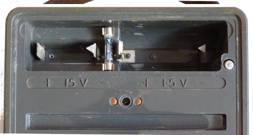
The steel clip shown here is used to keep the 1.5Volt cell in
place.
Insert 1.5V cell with positive towards the centre, the red dot
indicates how the 15V one should be inserted. 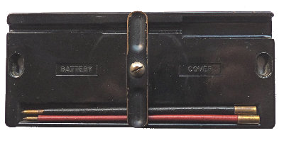 Note
that this cover unlike the one for the
Model 7 has an
additional slot for a spring loaded hook probe which is often missing. Note
that this cover unlike the one for the
Model 7 has an
additional slot for a spring loaded hook probe which is often missing.
|
Universal Avometer Model 8
(military versions)
AM stores numbers
10A/16411, 10S/16411, 10AF/96
(AM pattern AP12945)
|
This one
is the same as the model 8 Mk1 except that it is fitted with an
extended metal push button with rubber boot to reverse the moving coil.
This type of pushbutton was used on
some miitary versions but not all
and some if not all have a steel outer casing with an earthing
terminal. The one on the right is labelled 10AF/96
These instruments preceded the Test
Set No.1 (see below) which has ranges in multiples of 1 and 3 like the
model 9 rather than 1 and 2.5 of the model 8
Later versions of the model 8 with
this tyoe of push button were being made and labelled with 10S/16499 in
the late 1960s.
|
 |
Universal Avometer
Model 8 Mark II
Introduced 1956. This one described here was made in 1960
|
Added red and black banana terminals.
Added 500 volt DC range early in production.
The rectifier has been replaced in this instrument.
With the change to the familiar red and black terminals new
leads and
prods were made and the battery cover was a simple piece of metal with
two keyholes and a piece of expanded rubber to keep the 1.5 Volt cell
in place.
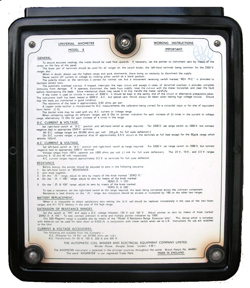
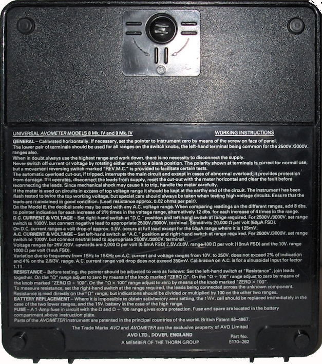
The following are both PDF files and will open in a separate window
Click
to download Instruction booklet
Click to download backplate instructions (the Mk1
and Mk2 had the same instructions)
Instruction plates for Mk1 Mk2 & Mk3 can be found
here
Model 8 UNIVERSAL AVOMETER Mk. II (from 1960 advert)
This instrument has been produced in response to a demand for a high
sensitivity version of the world-famous Model 7 AvoMeter. It follows
the standard design, retaining the traditional simplicity of operation
and compact portability. It has a sensitivity of 20,000 ohms per volt
on all D.C. ranges and 1,000 ohms per volt on A.C. ranges from 100 V
upwards.
In addition to the many well-known features such as the automatic
overload protection device, dual-knob range selection, etc., it has a
push-button for reversing the polarity of the movement to obviate the
inconvenience of changing over the leads when encountering opposite
potentials in respect to a common reference point.
CURRENT: A.C. and D.C. 0 to 10 amps.
VOLTAGE: A.C. and D.C. 0 to 2,500 volts. RESISTANCE: 0 to 20 megohms
(with internal batteries);,O to 200 megohms (with external D.C.
supply).
DECIBELS: -15 db to + 15 dB.
ACCURACY
Where applicable, all AvoMeters and AvoMinors meet the standards of
accuracy laid down in Section 6 of British Standard Specification
89/1954.
Shrouded plug in type leads are now supplied with all AvoMeters.
|
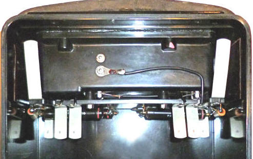
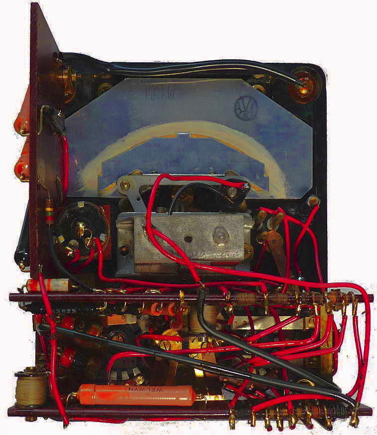
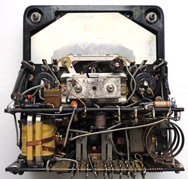
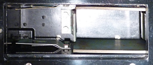
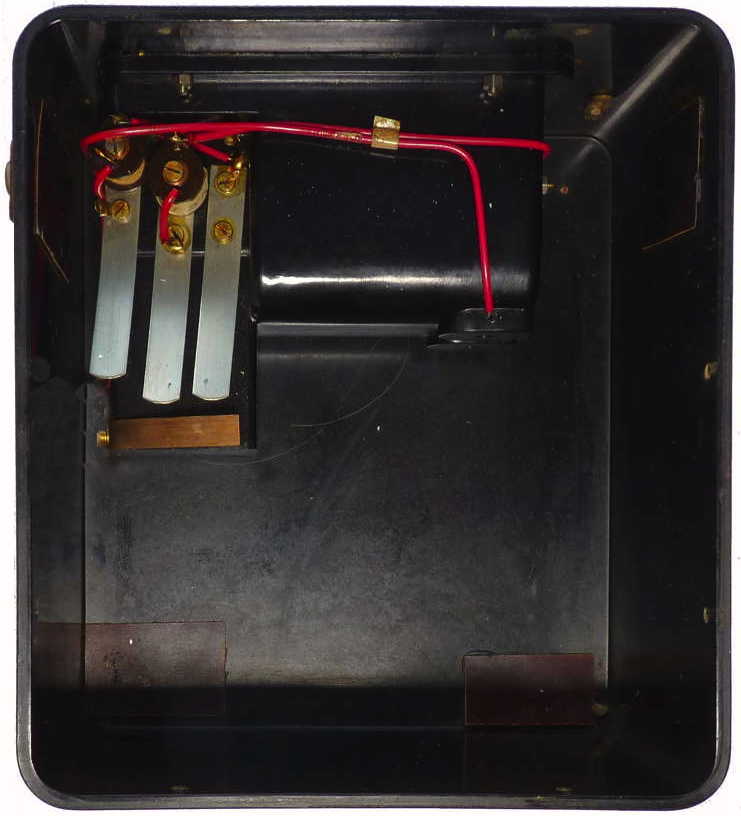
This is the inside of a model 8 Mk2 showing the four inner
leaf springs
which make connections between the battery compartment and the meter
movement and the two outer ones which make connections to the HV
terminals.
A similar arrangement is used on the model 7 and model 40 meters.
(click on image)
|
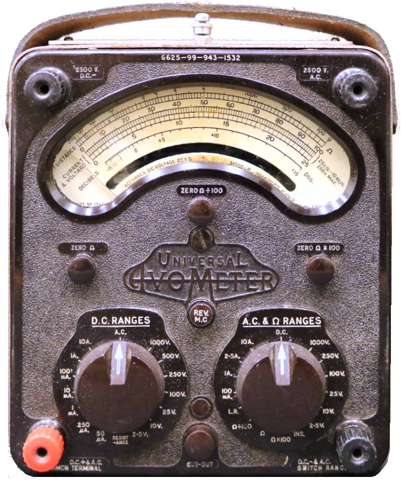
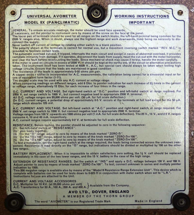
Universal
Avometer
Model 8X (Panclimatic)
|
A panclimatic version of the model 8 was introduced in the
early 1960s. Electrically and mechanically the same as the model 8 it
was a tropicalised version incorporating encapsulated components and
using materials resistant to mould growth. Under bright light as can be
seen on the image here the moulding material for the casing and knobs
has a brownish tinge.
The model 8X was also supplied in a steel screening case
referred to as the model 8SX.
The military version shown here is engraved with the NATO part
number 6625-99-943-1532
Later versions were given the title Test Set No.1
(see description below)
|
 |
Universal Avometer
Model 9 Mark II
Introduced in about 1964
|
The model 9 was intended for the export market and is similar
to the Model 8 MarkII apart from the international symbols and 3-10
ranges instead of 2.5-10 and the positioning of the anti parallax
mirror.
No dB scale; resistance on bottom of scale plate instead of
top; no LR or Ins. position
DC
3, 10, 30, 100, 300, 600, 1000, 3000 volts - sensitivity 50 uA
DC
0.05, 0.3, 1, 10, 100 mA, 1, 10
AC
3, 10, 30, 100, 300, 1000, 3000 volts - sensitivity:
1 mA on 100+ volts, 3 mA on 30, 10 mA on 10, 30 mA
on 3
AC
10, 100 mA, 1, 10 A
R
2k, 200k, 20 Mohm (20, 2k, 200k ohm center)
Click here for Instruction manual
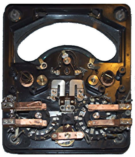
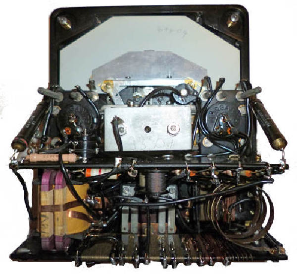
The rear of the front panel of a Model 8 MkII (the switching
arrangement for models 7,8 and 40 etc is much the same)
|
Battery compartment found on
Model 8 Mk2 and 9 Mk2 instruments.
Insert 1.5V cell with positive
towards the centre, the red dot indicates how the 15V one should be
inserted.
The Bakelite cover was changed to a simple metal part
with
keyholes on the Mk2 and Mk3 instruments (see below).
|
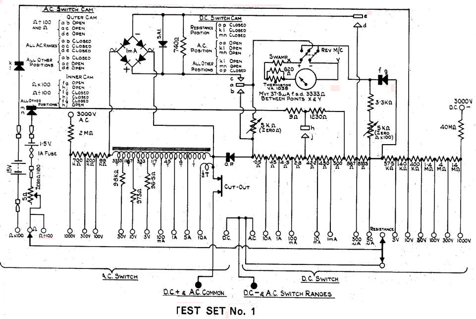
Test set No.1
(NATO part number 6625-99-105-7050)
military version of Model 8/9
Mark
II
This one described here was
made in 1971
Note that
Test set No1 was made for several years and was based upon the current
commercial model at the time.
(see model 8 Mk5 below)
|
Test set No.1 (a military version of Model 8/9 Mark 2)
Essentially the same as Model 8 Mark 2 apart from 3-10 ranges instead
of 2.5-10; no dB scale; resistance on bottom of scale plate instead of
top; no LR or Ins. positions. At some point added fuse on low ohms
ranges.
This model is housed in a protective steel case.
No dB scale;
resistance on bottom of scale plate instead of top, no
LR or Ins. positions
DC
3, 10, 30, 100, 300, 600, 1000, 3000 volts - sensitivity 50 uA
DC
0.05, 0.3, 1, 10, 100 mA, 1, 10 A
AC
3, 10, 30, 100, 300, 1000, 3000 volts -
sensitivity: 1 mA on 100+ volts, 3 mA on 30,
10 mA on 10, 30 mA
on 3
AC
10, 100 mA, 1, 10 A
R
2k, 200k, 20 M ohm (20, 2k, 200k ohm center)
Later versions of 'Test Set No. 1' were
essentially identical to the Mk 5 (to 1986)
and Mk 6 (from 1986 to
end of Avo use).
|
Battery Compartment. You can see that one fuse is a spare and
unconnected. The negative contact of mine is a bit green and you will
see that I have split open the case of the original battery to refill
with new button cells.
|
Universal Avometer
Model 8 Mark III
Introduced about 1964. This one is described
here
was made in 1968
This is a 1965 version: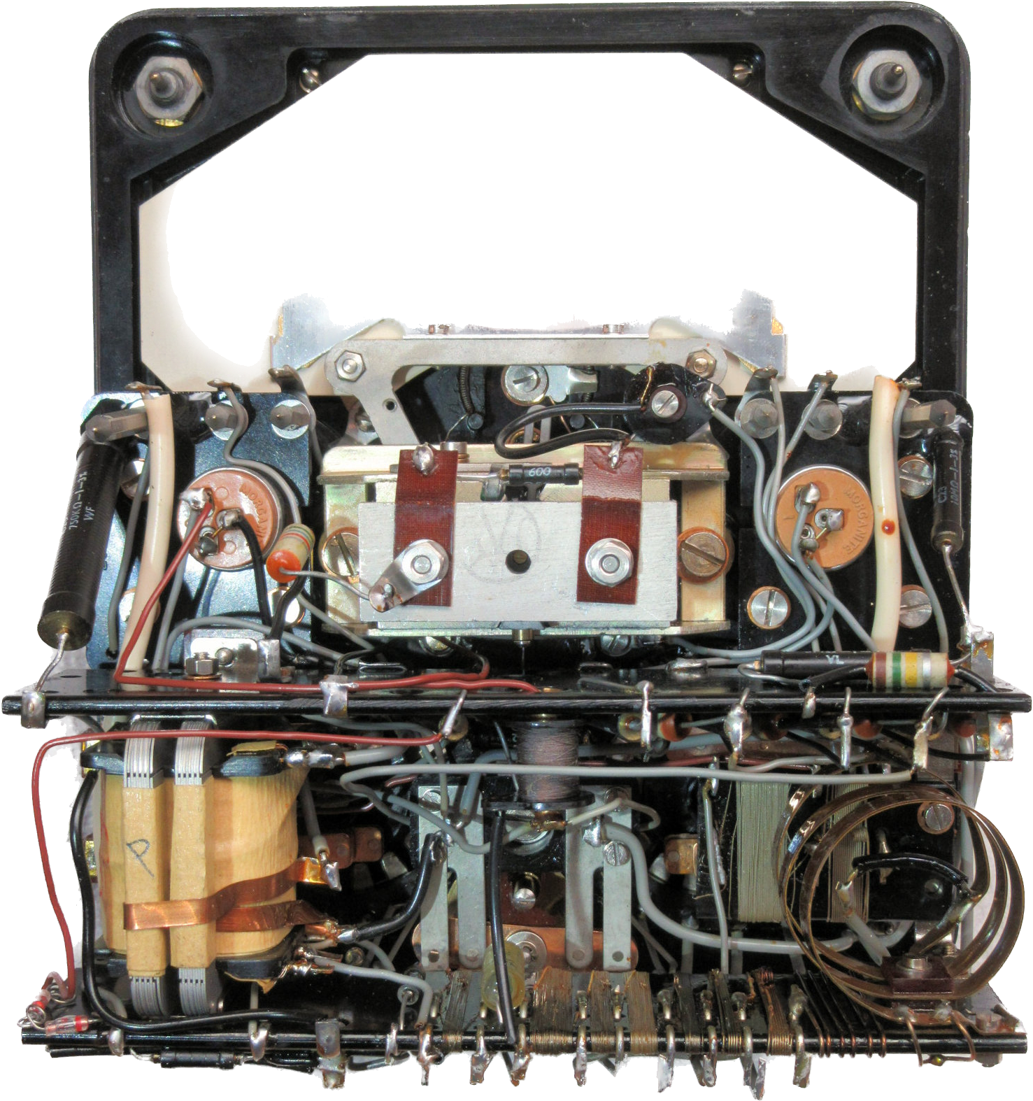
|
Replaced copper-oxide with germanium rectifiers to improve AC
sensitivity and frequency response (typically 20K Hz at 2.5V). These
were not incorporated in Model 9 until
the Mark 4 version.
Fuse added to low ohms ranges. Early models of the Mk3 do not
incorporate the additional protection features described below and
shown on the circuit diagram.
DC 2.5, 10,
25, 100, 250, 500, 1000, 2500 volts - sensitivity 50 uA
DC
0.05, 0.25, 1, 10, 100 mA, 1, 10 A
AC
2.5, 10, 25, 100, 250, 1000, 2500 volts -
sensitivity: 1 mA on 10+ volts, 10 mA on 2.5
AC
100 mA, 1, 2.5, 10 A
R
2k, 200k, 20 M ohm (20, 2k, 200k ohm center)
Also LR (= 0.325 volts, for use with low range of Resistance Range
Extension unit) and Ins. (2 M ohm
center, with external power)
A miltary version
of the 8Mk 3 (AM stores number 10S/16411) with extended Rev MC button
was also made like that shown on the earlier model above.
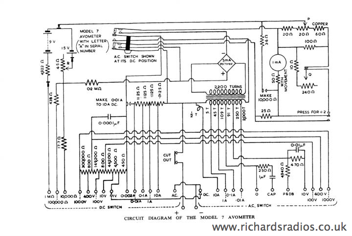
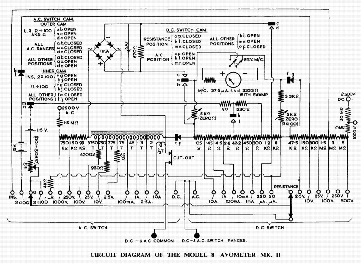
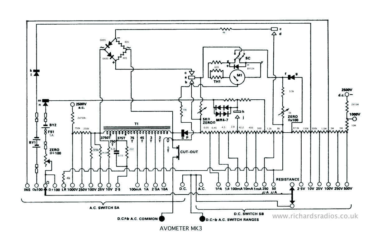
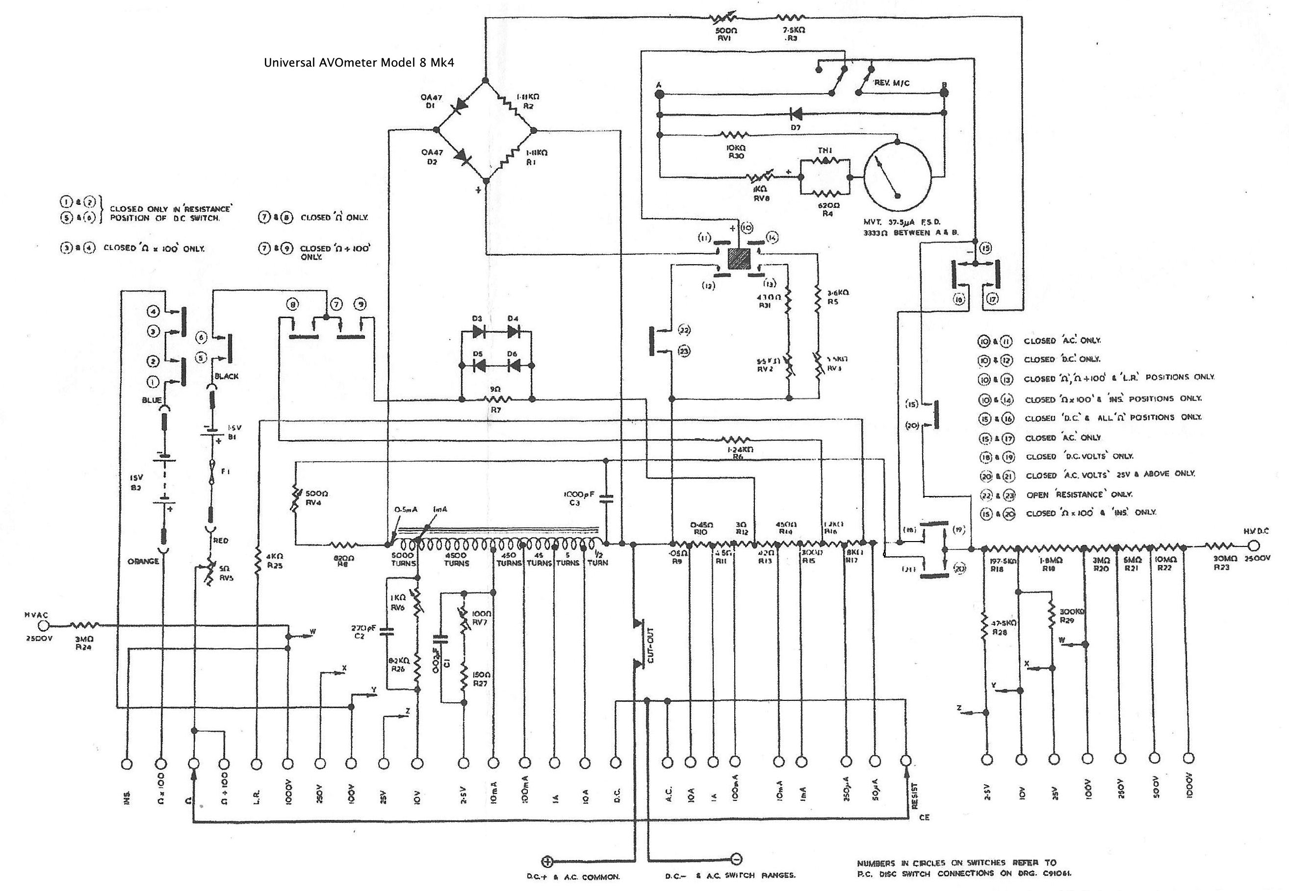
Looking at the diagram on the right
the meter has thermal compensation plus additional protection
diodes around the movement and in circuit with the ohms range. The ohms
range was vulnerable to putting it across AC so the diodes back to back
would protect the meter and draw the current through the fuse. Also a
diode across the movement deals with AC on a DC setting so protects the
movement, so it sees 1/2 the waveform thus tripping the mechanical
movement otherwise the movement would just see AC and not move
therefore not cut out and ultimately be destroyed. Previous models it
seems would not be protected if on the DC setting but were connected to
a high AC supply voltage.
|
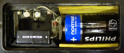
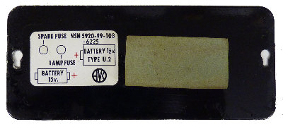
Note
the changes to the battery contacts and the shaped rubber spacer to
keep the 1.5 Volt battery in place to one side to make room for the
1Amp
fuse and spare.
Previous models often only had red
blobs of paint to indicate how the batteries should be inserted
(click on image)
|
Universal Avometer
Braille Model 8 Mark lll
|
This is a later and more sensitive
version of the Braille model7 shown above.
Have a look here for a description
and additional pictures of this model:
http://www.pa4tim.nl/?p=1833
|
|
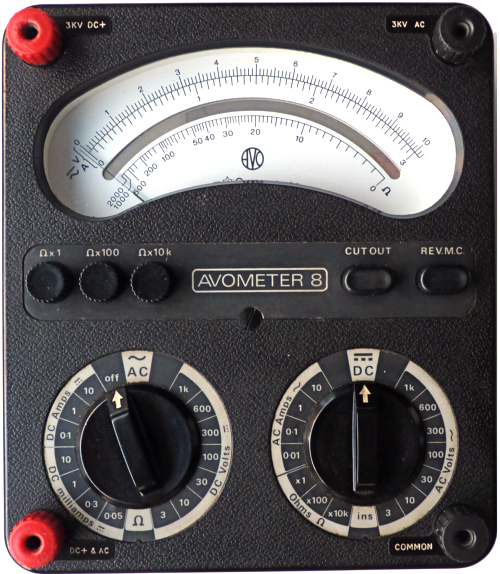
Universal Avometer
Model 8 Mark IV
Introduced 1969. This one described here
was made in 1971
In 1980 this instrument would have cost £98.50 exc VAT 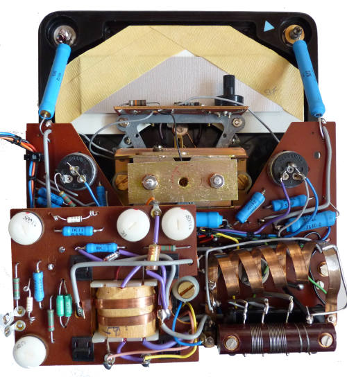
|
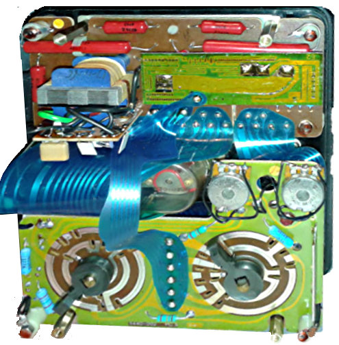
New internal construction using PC boards. Wired connections
to battery compartments.Reliability problems with this model (no
military versions). 2.5 A range replaced with 10 mA and resistance
moved to bottom of scale plate to match Model 9. AC sensitivity
increased again
DC 2.5, 10,
25, 100, 250, 500, 1000, 2500 volts - sensitivity 50 uA
DC
0.05, 0.25, 1, 10, 100 mA, 1, 10 A
AC
2.5, 10, 25, 100, 250, 1000, 2500 volts
sensitivity: 0.5 mA on 25+ volts, 1 on 10, 10 on 2.5
AC
10, 100 mA, 1, 10 A
R
2k, 200k, 20 M ohm (20, 2k, 200k ohm center)
Also LR (= 0.325 volts, for use with low range of Resistance Range
Extension unit) and Ins. (2 M ohm
center with external power
Housed in plastic case. Mirror placed mid scale rather than at
bottom
as on all previous versions. This was the last model to have leather
rather than plastic
carrying strap.
Avometer Model 8 Mk 4
(from 1970 catalogue}
This multi-range instrument has been designed to meet the requirements
of radio, television and electronic engineers requiring an accurate,
sensitive yet robust instrument. The Avometer Model 8 Mk 4 incorporates
all the traditional design features of its predecessors, so highly
valued for Simplicity, together with such additional features as:
increased sensitivity in the lower a.c. voltage ranges, fused ohms
circuit to provide increased protection against inadvertent overload in
the lower resistance ranges, improved temperature coefficient enabling
measurements up to 500 amps d.c. to be made with the aid of a range of
shunts, and improved frequency response. It also incorporates the
familiar Avo automatic cut-out mechanism and a decibel scale for audio
frequency tests.
SPECIFICATION
AC 10mA to 10A f.s.d. in 4 ranges.
DC 50uA to 10A f.s.d. in 7 ranges.
AC 2.5V to 2,500V f.s.d. in 7 ranges.
DC 2.5V to 2,500V f.s.d. in 8 ranges.
Resistance: 0 to 20M ohm(First indication 0.5ohm).
Decibels: -15dB to + 15dB.
Accuracy: AC Voltage and Current ±2.25% of f.s.d.
DC Voltage ±2% of indication. d.c. Current ±1% off.s.d.
Sensitivity: AC voltage ranges 2,000 ohms/V(10V upwards).
DC voltage ranges 20,000ohms/V (all ranges).
Size: 204 x 185 x 115 mm.
Weight: 2.95 kg. (including leads).
|
(click on image)
click
here for instruction
booklet
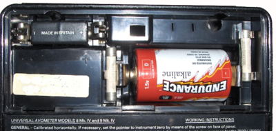
This is the first model to have
wired connection between the battery compartment and the meter. The
spare fuse is housed in a hole on the right. Access by
removing the back cover.
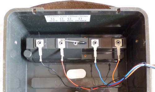
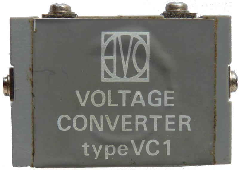 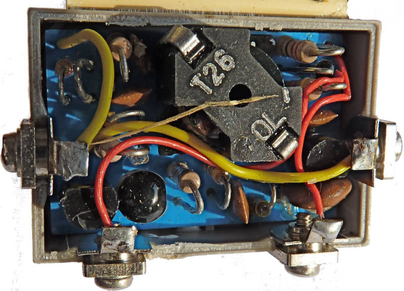
This meter was equipped with
an electronic
voltage converter which was supplied from the 1.5Volt
cell. This item is normally supplied with a flexible printed connector
though in my case the previous owner had soldered wires to the 1.5 Volt
cell to power the unit. See here for more
information.
|
Introduced 1969. This one described here has no date
|
Avometer Model 9 Mk 4
(from 1970 catalogue)
The Avometer Model 9 Mk. 4 is a high sensitivity instrument for the
measurement of voltage, current and resistance. It is designed
primarily for the electronics engineer and is similar in specification
to the Avometer Model 8 Mk. 4. The Model 9 incorporates all the
traditional design features of the Model 8 including the Avo automatic
cut-out mechanism and reverse moving coil facility.
The Model 9 is, however, scaled in basic units of 10 and 3 and all
range switches, controls and terminals are identified by graphical
symbols, which in general follow the requirements of the International
Electrotechnical Commission.
The protective devices incorporated in the Model 8 Mk. 4 are all
retained and an insulation resistance range now enables measurements
up to 600A to be made using a range of external shunts. The decibel
scale is, however, not included on this instrument.
SPECIFICATION
Similar to the Test set No 1 (see above)
A.C. 10mA to 10A f.s.d. in 4 ranges.
D.C, 50uA to 10A f.s.d. in 7 ranges.
A.C. 3V to 3000V f.s.d. in 7 ranges.
D.C. 3V to 3000V f.s.d. in 8 ranges.
Resistance: 0 to 20M a (first indication 0.5 ohm
Accuracy: A.C. Voltage and Current ±2.25% of f.s.d.
D.C. Voltage ±2% of indication. D.C. Current ±1% of f.s.d.
Sensitivity: A.C. Voltage Ranges 2000 ohms/volt (10V upwards).
D.C. Voltage Ranges 20,000 ohms/volt (all ranges).
Size: 204 x 185 x 115mm.
Weight: 2.85kg.
Price each £34.80
|
The case and battery compartment on
the later model 8Mk4 and model 9Mk4 are shown here. Similar to the
design adopted for the subsequent models.
|
|
Avometer Model
8 Mark V
Introduced 1972. This one described here
was made in 1973
Test
Set No1 Mk3 (6625-99-2822) is the military version of this
instrument
|
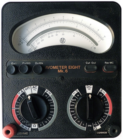
New
internal and external design including movement, the new plastic
front-panel no longer includes the word "Universal" Plastic casing
redesigned. Leather carrying handle
abandoned for a plastic one. Instrument much lighter than all previous
models.
dB scale and LR range deleted. (But LR could still be
measured with
Resistance Range unit.) Adopted Model 9 ranges and added 600 volts AC
range.
DC 3, 10, 30,
100, 300, 600, 1000, 3000 volts - sensitivity 50 uA
DC
0.05, 0.3, 1, 10, 100 mA, 1, 10 A
AC
3, 10, 30, 100, 300, 600, 1000, 3000 volts -
sensitivity: 0.5 mA on 30+ volts, 1 on 10, 10 on 3
AC
10, 100 mA, 1, 10 A
R
2k, 200k, 20 M ohm (20, 2k, 200k ohm center)
Also Ins. (2 M ohm center, with external power)
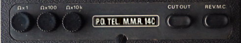
AVO METER MULTI RANGE MMR14C/2
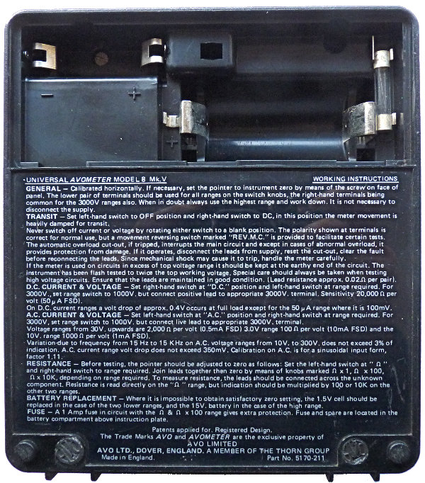
The Model 14C Avometer is a Model 8 Mk5 made to a
British Post Office specification. It is essentially the same apart
from front panel markings and a different instruction plate on the back.
A military version 'Test Set
No.
1' was essentially identical to the Mk 5 (to 1986) except for
the front panel markings shown here:
|
The battery compartment on the Mk4 and subsequent models was
accessed from the back rather than the top. The ribbed plastic housing
is used to surround the cylindrical 15
Volt battery and keep it in place. The spare fuse is in the centre.
|
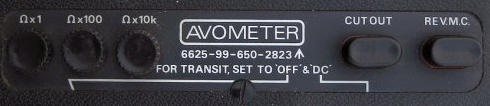
Avometer Model
8 Mark 6
Introduced early1980's This one described
here was
made in 1984
|
New internal design using rigid PC boards (less rugged)
instead of flexible wiring. Deleted high-voltage terminals.
DC 3, 10, 30,
100, 300, 600, 1000 volts - sensitivity 50 uA
DC
0.05, 0.3, 1, 10, 100 mA, 1, 10 A
AC
3, 10, 30, 100, 300, 600, 1000 volts -
sensitivity: 0.5 mA on 30+ volts, 1 on 10, 10 on 3
AC
10, 100 mA, 1, 10 A
R
2k, 200k, 20 M ohm (20, 2k, 200k ohm center)
Also Ins. (2 M ohm center, with external power)
The military version 'Test Set
No. 1' was essentially identical to the Mk 6
|
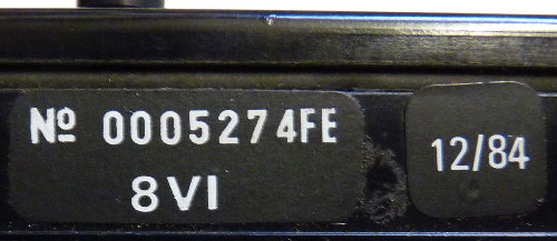
The serial number and date of manufacture on RHS of case
(first implemented on the Mk 4 instruments)
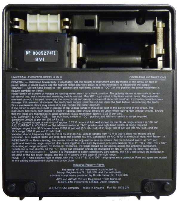
The ribbed plastic housing is used
to surround a cylindrical 15
Volt battery and keep it in place.
|
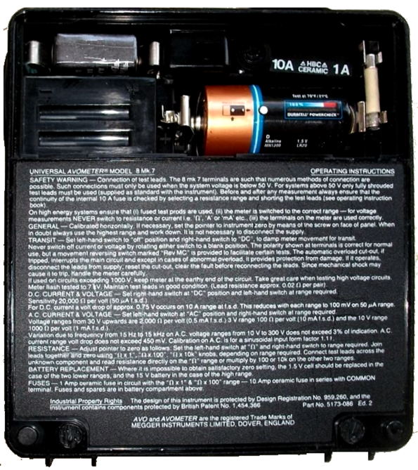
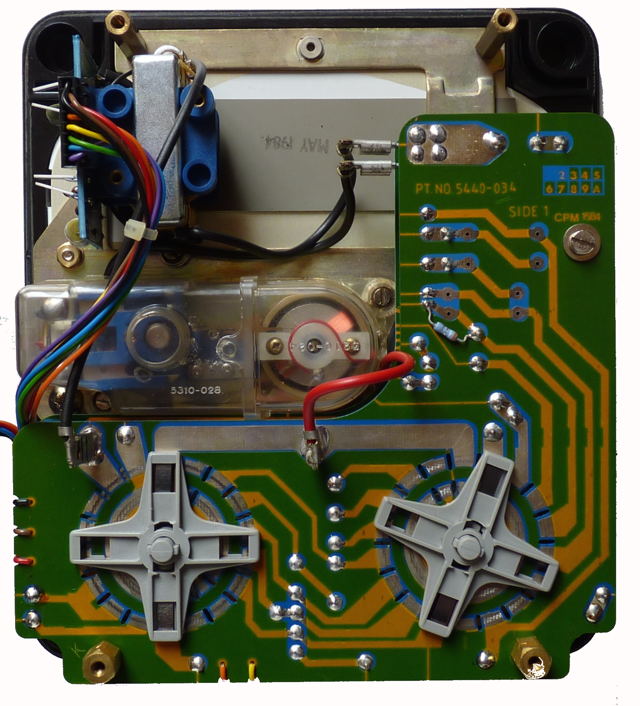
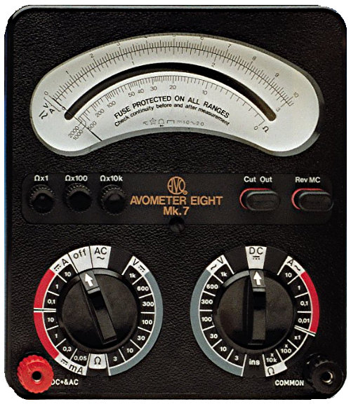
Avometer Model
8 Mark 7
Introduced 1992
|
Only change from the Mark 6 was the addition of a 10 A fuse in
series with all ranges.
Last manufactured 2008.
|
Click
here to view the AVO
8
Mk7 USER
GUIDE
Click here to
view the AVO 8 Mk7 DATA SHEET
|
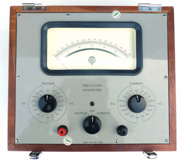
Precision Avometer
Introduced 1963/4 This one in described
here
was made in 1967
|
RANGES
DC
1.5V to 1500V and 1.5mA to 15A
AC 3V to 1500V and 3mA to 15A
Sensitivity 100 Ohms/Volt on DC and AC except for 3V AC range which is
50mA fullscale
|
Designed to provide an
accurate and stable local reference or transfer standard for industrial
and laboratory engineers. It meets the requirements of Section 6 of BSS
89/1954 for precision grade instruments ie:
D.C. Voltage ranges 0.3% of f.s.d.
D.C. Current ranges 0.5% of f.s.d
The accuracy on a.c. voltage and current ranges is 0.75% of FSD (form
factor of 1.11) This accuracy is maintained for audio frequency tests
up to 1 kHz on ranges up to 3OOV.
Temperature correction:
true value= 1+.0003(t-20) where t is ambient temperature in degrees
Celsius
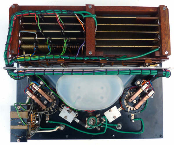
Range selection is accomplished by means of two controls
mechanically interlocked with the
third
central control to select voltage or current as required. Two 7 inch
scales calibrated 0
to 150 and 0 to 30 cover both voltage and current measurements. A test
certificate is provided for each instrument housed in the lid. (not
shown)
|
|
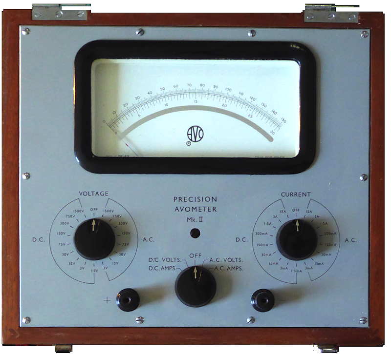
Precision Avometer Mk2
made in June 1970
|
Pictures of Mk2 version supplied by Adrian Almond
|
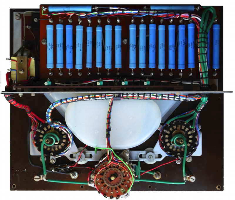
The Welwyn blue high stability precisiion resistors were
introduced by AVO in about 1968 to replace the wire wound types used on
previous models throughout their range.
|
Notes
|
|
|
|
Just to give you all an idea of variants of the Avometer.
There are some interesting variants here that may have only ever had
small production runs. Thanks to Andy Gilham (Megger/AVO) for this list
of official variants. Please be aware that the number of build variants
actually runs into 100s, with different component values, lacquer
changes, number of windings on the transformers....etc.
Avometer Model 1
Avometer Model 2
Avometer Model 3
Avometer Model 4
Avometer Model 5
Avometer Model 6
Avometer Model 7
Avometer Model 7x
Avometer Model 7sx
Avometer Model 7 (Braille)
Avometer Model 7 (London University Special)
Avometer Model 7 Mk 2
Avometer Model 7x Mk 2
|
Avometer Model 8
Avometer Model 8R
Avometer Model 8x
Avometer Model 8s
Avometer Model 8sx
Avometer Model 8sv
Avometer Model 8sv (Special)
Avometer Model 8 (Braille)
Avometer Model 8 Mk 2
Avometer Model 8x Mk 2
Avometer Model 8sx Mk 2
Avometer Model 8 Mk 3
Avometer Model 8 Mk 3 (Braille)
Avometer Model 8x Mk 3
Avometer Model 8sx Mk 3
Avometer Model 8 Mk 4
Avometer Model 8x Mk 4
Avometer Model 8 Mk 5
Avometer Model 8 Mk 6
Avometer Model 8 Mk 7
|
Avometer Model 9
Avometer Model 9sx
Avometer Model 9x
Avometer Model 9s
Avometer Model 9 Mk 2
Avometer Model 9sx Mk 3
Avometer Model 9 Mk 4
Avometer Model 40
Avometer Model 40 (Braille)
Avometer Model 40x
Avometer Model 40sx
Avometer Model 40x Mk 2
Avometer Model 47A
Avometer Model 47As
Avometer Model 48A
Avometer Model Type D
Avometer Model HR1
Avometer Model HR2
Avometer Model HR3
Avometer Model HS1
Avometer Model HS2
Avometer Model Multirange Test Set No.1
Avometer Model Multirange Test Set No.2
Avometer Model Multirange Test Set No.3
OY Universal Test Meter Unit No. 107
|
|
Each model is assumed to have been discontinued when the next
of that
model was introduced, except that the DC Avometer was produced in
parallel with the Universal until the Model 40 replaced both in 1939,
just after the start of the war. Also, some of the military versions
persisted longer due to specifications.
The Model 8/9 was not intended to be a replacement for the Models 7 or
40 outside of electronic work. Aside from the different ranges and
sensitivity, the 8/9 were less accurate, at least until the Mark 5
which represented a significant improvement (it was still slightly
worse on high resistances due to not having a Q knob, and on all
resistances due to ranging by factors of 100 rather than 10). The 8/9
also took considerably more voltage on DC current ranges; due to the
universal shunt being the same as used for voltage, the burden on
current ranges other than the lowest had to be at least 4 times that of
the movement, i.e. 0.5 V before the Mark 5 and later 0.4 V.
|
The above list indicates only ranges found on the front panel.
Additional usable ranges as follows:
The lowest DC current range could also be used as a
millivolt range. This was 100 mV on the Model 8 Mark 5+, 125 mV on the
earlier Model
8/9's, and 100 mV on the Model 7
On the DC AVOmeter, Universal AVOmeter, and
Model 40, the reverse
could be done and the lowest DC
voltage range (120 mV) be used
as a current range (6 mA).
Higher resistances could be measured with external
power, and zeroed using the Q knob. On the Model 7, the 100 and 400
volt ranges could be used as the '10 and 40 megohm' ranges (50k and
200k
center). The adjustment range of the Q knob was wide enough to use 240v
mains on
the former. The Model 40 was similar, having a stated '1 megohm' range
using the
120 volt range (again 240v mains could be used).
|
Click on image for details of instruments and accessories
available in 1953
|
|
Acknowledgments
Images other than those of the meters in my possession have
been
gleaned, cleaned up and resized from various sites on the internet.
Others including Paul Thomas, Dave Philpott, Hans Caluwaerts and Sean
Mckinney have made
comments and
provided
information which has now been included.
|
The
basic details of the instruments have been compiled and provided by
Andrew
Usher who felt that there was a need for an AVO page similar to that
for Simpson meters shown here: www.simpson260.com
|
last
revision 18/09/2022
|


